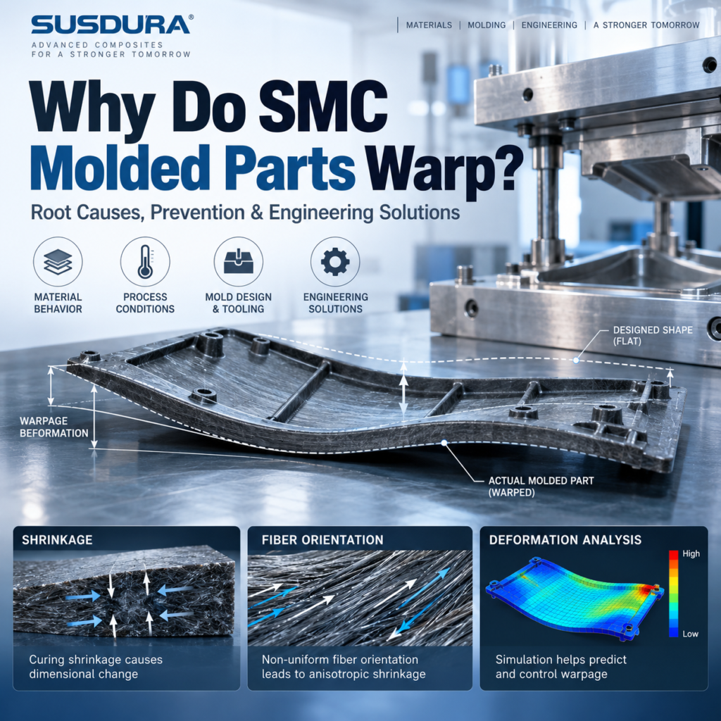
SMC warpage is a critical challenge in precision compression molding, especially when manufacturers must maintain tight dimensional tolerances across complex geometries and high-volume production. SMC molded parts warping may occur immediately after demolding, during cooling, or between production batches. Understanding SMC warpage causes requires examining SMC shrinkage, differential shrinkage, residual stress, and fiber orientation together. This guide explains practical SMC warpage solutions and how manufacturers can achieve consistent SMC dimensional stability.
TL;DR: Key Engineering Findings
SMC warpage is primarily a differential deformation problem. Chemical shrinkage, thermal contraction, fiber orientation and mechanical constraints interact to produce distortion.
Material formulation alone cannot eliminate warpage. Even low-shrinkage SMC can deform when flow patterns, curing conditions or part geometry are unbalanced.
SMC fiber orientation is critical. Flow-induced fiber alignment creates direction-dependent stiffness and thermal expansion behavior.
Reliable troubleshooting requires measurement. Compare geometry at defined intervals after demolding, investigate material and processing records, and validate changes through dimensional inspection.
Long-term dimensional stability requires an integrated approach: Material Formulation + Tooling Design + Compression Molding Control + Dimensional Validation.
1. What Is SMC Warpage and How Does It Affect Molded Parts?
SMC warpage refers to unwanted deformation of a Sheet Molding Compound component from its intended geometry. Unlike uniform SMC shrinkage, which produces a relatively consistent reduction in dimensions, warpage creates non-uniform bending, twisting, bowing or angular distortion.
This distinction is essential in precision composite manufacturing.
An SMC component can exhibit acceptable overall shrinkage while failing a flatness or parallelism requirement. Conversely, a part may remain relatively flat but experience unacceptable dimensional deviation due to uniform shrinkage.
Common forms of SMC molded parts warping include:
Bowing: Curvature along a flat panel or structural wall.
Twisting: Rotational deformation between opposite corners.
Corner lifting: Localized distortion at unsupported edges.
Wall distortion: Inward or outward movement of ribs, flanges or vertical walls.
These defects frequently become apparent after demolding and cooling. Some dimensional changes may also develop during subsequent thermal exposure or storage, particularly when cure completion, moisture effects or stress relaxation remain relevant.
For electrical insulation components, even moderate warpage can create assembly difficulties. A distorted circuit breaker frame may misalign mounting interfaces, while a warped electrical enclosure panel may compromise sealing compression.
Therefore, dimensional stability must be evaluated using more than overall length and width.
Flatness, parallelism, angularity, hole position and functional assembly dimensions should be included in the inspection plan.
[Suggested Figure: Four Typical Types of SMC Warpage — bowing, twisting, corner lifting and wall distortion.]
Alt text: Four common SMC compression molding warpage defects affecting dimensional accuracy and assembly performance.
Key Takeaways
Shrinkage and warpage are related but fundamentally different dimensional phenomena.
Functional tolerances are often more important than overall dimensional shrinkage.
Warpage inspection should account for geometry and measurement timing.
Internal Link: Learn more about SUSDURA composite product design and dimensional engineering.
2. The Science Behind SMC
The fundamental mechanism of SMC warpage is non-uniform strain developing within a molded component.
During SMC compression molding, the resin matrix undergoes chemical curing while the material experiences temperature changes, pressure, and fiber redistribution.
Three mechanisms are particularly important.
Chemical Cure Shrinkage
Thermosetting resins undergo cross-linking reactions during curing. The resulting chemical structure may occupy less volume than the original reactive material.
Low-profile additives can compensate for part of this contraction through controlled phase and morphological changes, but the resulting behavior depends on the complete formulation.
Thermal Contraction
SMC components are generally molded at elevated temperatures and subsequently cool toward ambient conditions.
The resin matrix and glass fibers have different coefficients of thermal expansion. Their combined contraction is influenced by fiber content, orientation, filler loading and the effective properties of the cured composite.
When different regions cool or contract unequally, internal stresses can develop.
Anisotropic Shrinkage
SMC contains discontinuous reinforcing fibers whose orientation changes during mold filling.
Because glass fibers restrict deformation differently along and across their orientation, the material may exhibit direction-dependent shrinkage and thermal expansion.
This is known as anisotropic behavior.
When one region of a component contracts differently from another, the resulting strain incompatibility can generate internal bending moments.
These stresses may remain partially constrained inside the molded component.
After demolding, mechanical constraints are removed, allowing some residual stress to relax through deformation.
Consequently:
Non-uniform Fiber Orientation + Cure Shrinkage + Thermal Contraction + Structural Constraints = Potential SMC Warpage
The exact contribution of each mechanism varies with compound composition, geometry and processing conditions.
The relationship between initial molding shrinkage and subsequent dimensional change can be investigated using ISO 2577:2007 — Thermosetting Moulding Materials: Determination of Shrinkage.
[Suggested Figure: Relationship Between Fiber Orientation, Differential Shrinkage, Residual Stress and Final Warpage.]
Alt text: Engineering diagram explaining how anisotropic SMC shrinkage and residual stress produce molded part warpage.
Key Takeaways
SMC differential shrinkage is a major source of dimensional distortion.
Fiber orientation influences stiffness and direction-dependent contraction.
Residual stress can contribute to deformation after mold release.
Internal Link: Explore SUSDURA’s composite material and process engineering capabilities.
3. Seven Major Causes of SMC Warpage
7 Major Causes of SMC Warpage
Explore the key factors affecting dimensional stability in SMC compression molding. Click each cause to discover its effects and engineering solutions.
Glass Fiber Orientation
During compression molding, material flow changes the orientation of reinforcing fibers. Different fiber directions create unequal shrinkage and stiffness throughout the molded component.
Directional bowing, twisting and uneven shrinkage.
Review material flow paths and optimize charge placement to improve fiber distribution.
SMC warpage is rarely caused by a single variable. Consistent dimensional stability requires coordinated control of material formulation, tooling, compression molding and cooling.
Understanding SMC warpage causes requires analyzing material behavior, tooling, processing and component geometry as an interconnected manufacturing system.
1. Non-Uniform Glass Fiber Orientation
During compression molding, SMC flows from its initial charge location into the remaining mold cavity.
This movement redistributes and reorients reinforcing fibers.
Different fiber orientation patterns may create unequal shrinkage, stiffness and thermal expansion across the component.
Long flow paths, complex ribs and abrupt section transitions can increase local orientation differences.
2. Inappropriate SMC Formulation
SMC dimensional stability depends on the balance between resin, low-profile additives, glass fibers, fillers and curing chemistry.
Excessive or insufficient shrinkage compensation can influence dimensional accuracy, surface quality and internal stress development.
A formulation optimized for one geometry may not perform identically in another.
3. Uneven Mold Temperature
Differences between upper and lower mold temperatures, or localized thermal variations, can change reaction rates and thermal histories.
Where cure development and thermal contraction differ, the component may develop an unbalanced stress distribution.
Mold surface temperatures should therefore be verified under representative production conditions.
4. Poor SMC Charge Placement
Charge geometry and placement determine the material flow path during mold closing.
An unbalanced charge pattern can produce excessive directional flow, non-uniform fiber orientation and inconsistent cavity filling.
5. Inadequate Curing Conditions
Insufficient curing may leave the material vulnerable to further dimensional changes.
However, simply extending curing time or increasing temperature does not guarantee improvement.
The objective is to establish a validated curing window for the selected compound and geometry.
6. Unbalanced Part and Mold Design
Sudden wall-thickness transitions, asymmetrical ribs, large unsupported surfaces and concentrated structural features can create non-uniform stiffness.
These geometric differences influence how internal stresses produce visible deformation.
7. Improper Demolding and Cooling
Premature ejection, uneven mechanical support or uncontrolled handling can deform a component before it develops sufficient dimensional stability.
Large thin-wall components can be especially sensitive to unsupported cooling.
SMC Warpage Root Cause Matrix
| Potential Cause | Typical Symptom | First Diagnostic Check | Possible Corrective Action |
|---|---|---|---|
| Fiber orientation | Directional bowing | Charge and flow pattern | Optimize charge layout |
| Formulation imbalance | Repeated dimensional variation | Material shrinkage data | Reformulate and validate |
| Temperature imbalance | Asymmetric deformation | Mold temperature mapping | Balance heating zones |
| Charge placement | Localized warpage | Charge position records | Adjust charge geometry |
| Cure inconsistency | Post-demolding changes | Cure evaluation | Validate cure window |
| Structural imbalance | Corner lifting or twisting | CAD and geometry review | Modify ribs or thickness |
| Cooling and ejection | Deformation after release | Demolding and cooling audit | Improve part support |
4. How to Diagnose SMC Warpage Before Changing Molding Parameters
A common troubleshooting mistake is adjusting mold temperature, pressure and curing time simultaneously.
Although this may occasionally improve the final part, it becomes difficult to identify which variable produced the result.
A systematic diagnostic process should begin with dimensional evidence.
Step 1: Establish the Actual Deformation Pattern
Measure the finished component against the approved drawing.
Identify whether the defect is bowing, twisting, flatness deviation, wall deformation or local dimensional displacement.
Use a defined datum strategy and repeatable fixturing conditions.
Step 2: Compare Dimensions at Different Stages
Evaluate the component after demolding, after a specified cooling interval and after a defined stabilization period.
For parts susceptible to thermal deformation, additional measurements may be performed after controlled temperature exposure.
The measurement schedule should be consistent between samples.
Step 3: Review Material Consistency
Compare resin formulation, glass fiber content, sheet weight, material maturation and storage records.
Batch-to-batch changes in flow behavior can influence fiber redistribution and dimensional results.
Step 4: Review Tooling and Process Records
Check mold temperatures, charge weight, charge placement, closing sequence, pressure profile and curing time.
Compare acceptable and defective production lots wherever possible.
Step 5: Conduct Controlled Trials
Change one primary process variable at a time, while holding other relevant conditions constant.
Where interactions are suspected, a structured design of experiments may be more effective than isolated single-factor trials.
CMM inspection should then be used to evaluate the resulting dimensional distribution.
The diagnosis is complete only when the proposed cause and corrective action are supported by repeatable measurements.
5. Engineering Solutions to Prevent Warpage in SMC Compression Molding
Effective SMC warpage solutions should address the mechanism responsible for distortion rather than relying on a single universal processing adjustment.
A. Optimize SMC Material Formulation
Low-shrinkage and low-profile SMC formulations can help reduce dimensional variation.
However, resin chemistry, shrinkage-control additives, mineral fillers, fiber length and glass content must be evaluated together.
An increase in glass fiber content does not necessarily produce a proportional improvement in dimensional stability.
Excessive reinforcement or unsuitable material flow can introduce orientation-related distortion.
Material development should therefore include both standardized specimen testing and representative molded-component validation.
B. Optimize Mold and Component Design
Balanced wall thickness, suitable rib geometry and carefully designed transition regions can reduce structural asymmetry.
Heating systems should provide appropriate thermal uniformity across critical mold regions.
Where geometry-driven deformation is repeatable, validated mold compensation may be considered.
However, mold compensation should not be used to conceal unstable material or process conditions.
C. Control Compression Molding Conditions
Charge placement should be designed to manage material flow and fiber redistribution.
Mold temperature, closing speed, pressure and cure duration should operate within a validated process window.
Pressure alone cannot correct an unsuitable fiber architecture or unbalanced cavity filling pattern.
The best process is not necessarily the one producing the flattest individual trial part, but the one delivering consistent dimensional results across production conditions.
D. Control Post-Molding Deformation
Large or thin-wall parts may benefit from controlled ejection and supported cooling.
Cooling fixtures can help maintain geometry when appropriately designed and validated.
Dimensional inspections should take place after a defined stabilization interval, rather than relying exclusively on measurements made immediately after demolding.
Industry tolerancing principles are provided in ISO 20457:2026 — Plastics Moulded Parts: Tolerances and Acceptance Conditions, which addresses geometric and dimensional tolerancing for molded plastics, including thermosets. Applicable acceptance conditions must still be agreed for each component.
Key Takeaways
SMC warpage prevention requires coordinated material, tooling and processing decisions.
Low-shrinkage material reduces one source of variation but cannot eliminate all deformation.
A validated production window is more valuable than an isolated successful molding trial.
6. Real Engineering Case Study: Dimensional Stability Control for a Precision SMC Circuit Breaker Frame
Project Background
One relevant example from SUSDURA’s manufacturing experience involves precision SMC insulating frames used in air circuit breaker assemblies for an international electrical equipment customer.
These components require a combination of mechanical integrity, electrical insulation performance and reliable dimensional consistency.
Unlike simple flat composite panels, circuit breaker frames may contain mounting interfaces, reinforcing ribs, localized load-bearing features and complex structural geometry.
Their dimensional accuracy directly affects downstream assembly.
Engineering Challenge
The central challenge is maintaining consistent molded geometry across commercial production.
Even where the selected material meets its mechanical and electrical specifications, variation in shrinkage, fiber redistribution or processing conditions can affect critical dimensions.
For this type of application, dimensional control cannot be treated as a final inspection activity alone.
It must be incorporated into material selection, mold engineering and manufacturing validation.
Integrated Manufacturing Strategy
SUSDURA’s approach combines several related control areas.
Material engineering: Low-shrinkage SMC formulation selection and material batch consistency are important starting points.
Tooling engineering: Mold geometry, shrinkage allowance and dimensional inspection support accurate component development.
Compression molding: Standardized charge placement, curing parameters and operating procedures help control process variation.
Dimensional validation: CMM measurements provide objective evidence of conformity for defined critical features.
Production Quality Evidence
For its precision ACB frame application, SUSDURA has previously reported a process capability index of Cpk = 1.66 for a monitored dimensional characteristic.
This illustrates the importance of evaluating statistical process consistency rather than depending exclusively on individual passing measurements.
However, Cpk must always be interpreted with the corresponding characteristic, specification limits, measurement method, sampling period and process-stability evidence.
A single Cpk result does not prove that every dimension is capable or that warpage has been eliminated.
Engineering Lessons
This project demonstrates the broader requirements of precision SMC manufacturing: material formulation, tooling accuracy, process repeatability and dimensional validation must work together.
It is presented as a dimensional-stability manufacturing example, not as a documented before-and-after warpage failure investigation.
No unverified initial warpage measurements or corrective-action improvements are claimed.
[Suggested Figure: Precision SMC Circuit Breaker Frame — Product Geometry, Critical Dimension Locations and CMM Inspection.]
Alt text: SUSDURA precision SMC circuit breaker insulation frame showing dimensional inspection and production quality control.
[Suggested Table: ACB Frame Dimensional Validation Record — Characteristic, Drawing Tolerance, Sample Size, Measured Results and Process Capability.]
Key Takeaways
Precision electrical components require controlled geometry as well as material performance.
CMM results and process capability analysis support evidence-based quality validation.
Stable manufacturing depends on controlling the entire material-to-component process.
7. How SUSDURA Controls SMC Dimensional Stability in Mass Production
For international OEM customers, SMC dimensional stability must remain consistent beyond prototype approval and initial tooling trials.
Repeatability across raw material batches, production shifts and extended manufacturing periods is essential.
SUSDURA integrates material production, tooling development, compression molding and dimensional inspection to support this requirement.
Controlled SMC Material Manufacturing
SUSDURA uses automated material dosing and online X-ray sheet-weight monitoring to support consistent SMC sheet production.
Weight monitoring helps identify sheet-mass variation that could influence charging consistency.
However, uniform sheet weight is only one input to dimensional stability. It does not independently establish uniform fiber orientation or guarantee a warp-free finished part.
In-House Tooling and Dimensional Inspection
Tooling development incorporates component geometry, molding shrinkage, heating arrangements and ejection requirements.
SUSDURA also uses CMM inspection to evaluate mold and finished-component dimensions.
This provides an important feedback loop between design intent, tooling geometry and actual molded results.
Standardized Compression Molding
Controlled production parameters, initial-piece approval, routine dimensional checks and batch traceability help identify deviations before they become persistent production problems.
For precision applications, critical dimensions should be reviewed using appropriate statistical process control methods.
Engineering Validation Before Mass Production
A production-ready SMC component should be evaluated using the actual approved material grade, intended tooling and representative processing conditions.
Where dimensional stability is critical, validation should also consider cooling conditions, measurement timing and potential environmental exposure.
The objective is not to eliminate every microscopic dimensional change.
It is to maintain dimensional variation within agreed functional limits throughout the intended manufacturing process.
Key Takeaways
Stable raw material production supports repeatable molding but cannot replace finished-part inspection.
Material, tooling and production records should be traceable.
Dimensional validation must reflect actual production and functional requirements.
8. SMC Warpage Prevention Checklist for Engineers and OEM Buyers
SMC warpage prevention is most effective when dimensional risks are reviewed before mold construction and again during production qualification.
For engineers preparing a new SMC component, the following checklist provides a practical starting point.
| Evaluation Area | Essential Verification |
|---|---|
| Material formulation | Shrinkage behavior, fiber content and batch consistency |
| Material preparation | SMC sheet weight, storage and maturation conditions |
| Component design | Wall thickness, structural symmetry and rib configuration |
| Tooling design | Heating uniformity, cavity dimensions and ejection |
| Charge placement | Charge weight, coverage and flow direction |
| Molding parameters | Temperature, closing sequence, pressure and cure |
| Cooling control | Ejection timing, mechanical support and measurement interval |
| Dimensional inspection | Flatness, critical dimensions and datum strategy |
| Quality assurance | Traceability, repeatability and capability evidence |
For new projects, customers should provide both nominal dimensions and the functional reasons behind critical tolerances.
For example, a sealing surface may require stringent flatness, while a nonfunctional external wall may permit a wider geometric tolerance.
These differences should influence material selection, tooling design, manufacturing controls and inspection planning.
Manufacturers should also consider production feasibility. Unnecessarily tight tolerances can increase scrap, tooling complexity and inspection cost without improving component performance.
The most effective supplier evaluation therefore considers engineering capability rather than press tonnage or material price alone.
Key Takeaways
Dimensional requirements should be established before tooling development.
Acceptance criteria must reflect component function and realistic production capability.
Qualified suppliers should demonstrate material, tooling, processing and measurement competence.
Frequently Asked Questions About SMC Warpage
1. Can low-shrinkage SMC completely eliminate warpage?
No. Low-shrinkage SMC reduces selected shrinkage-related effects, but warpage may still result from uneven fiber orientation, mold temperature differences, structural asymmetry, residual stress or improper cooling. Material formulation must therefore be validated alongside tooling design and processing conditions.
2. Why do SMC parts warp after demolding?
SMC parts may warp after demolding because removal of mold constraints permits internal stresses to redistribute. Subsequent cooling, incomplete curing or unsupported handling can produce further dimensional changes. Comparing measurements taken at defined intervals helps identify the stage at which deformation occurs.
3. How does glass fiber orientation affect SMC dimensional stability?
Glass fibers restrict deformation more strongly along certain directions. During compression molding, material flow can create different local fiber orientation patterns. These variations influence effective stiffness, thermal expansion and shrinkage, potentially producing non-uniform deformation and warpage.
Conclusion: Achieving Consistent, Low-Warpage SMC Parts
SMC warpage is not simply a molding pressure or temperature problem. It is an engineering challenge involving SMC shrinkage, SMC differential shrinkage, SMC residual stress, SMC fiber orientation, material formulation and component geometry.
Understanding the mechanisms behind SMC molded parts warping allows manufacturers to distinguish true SMC warpage causes from secondary symptoms. Effective SMC warpage solutions require controlled material development, balanced tooling, validated processing and repeatable dimensional inspection.
For manufacturers facing SMC compression molding defects, long-term SMC dimensional stability should be established through documented engineering validation rather than repeated trial-and-error adjustments.
Work With SUSDURA — Engineered SMC Materials and Precision Compression Molding
SUSDURA provides integrated engineering support for low-shrinkage SMC materials, precision compression molds and custom composite components.
Our capabilities cover material formulation, product design, tooling development, compression molding, dimensional inspection and commercial production.
If you are experiencing SMC warpage, dimensional variation or assembly issues, our engineering team can review your component requirements and evaluate potential manufacturing solutions.