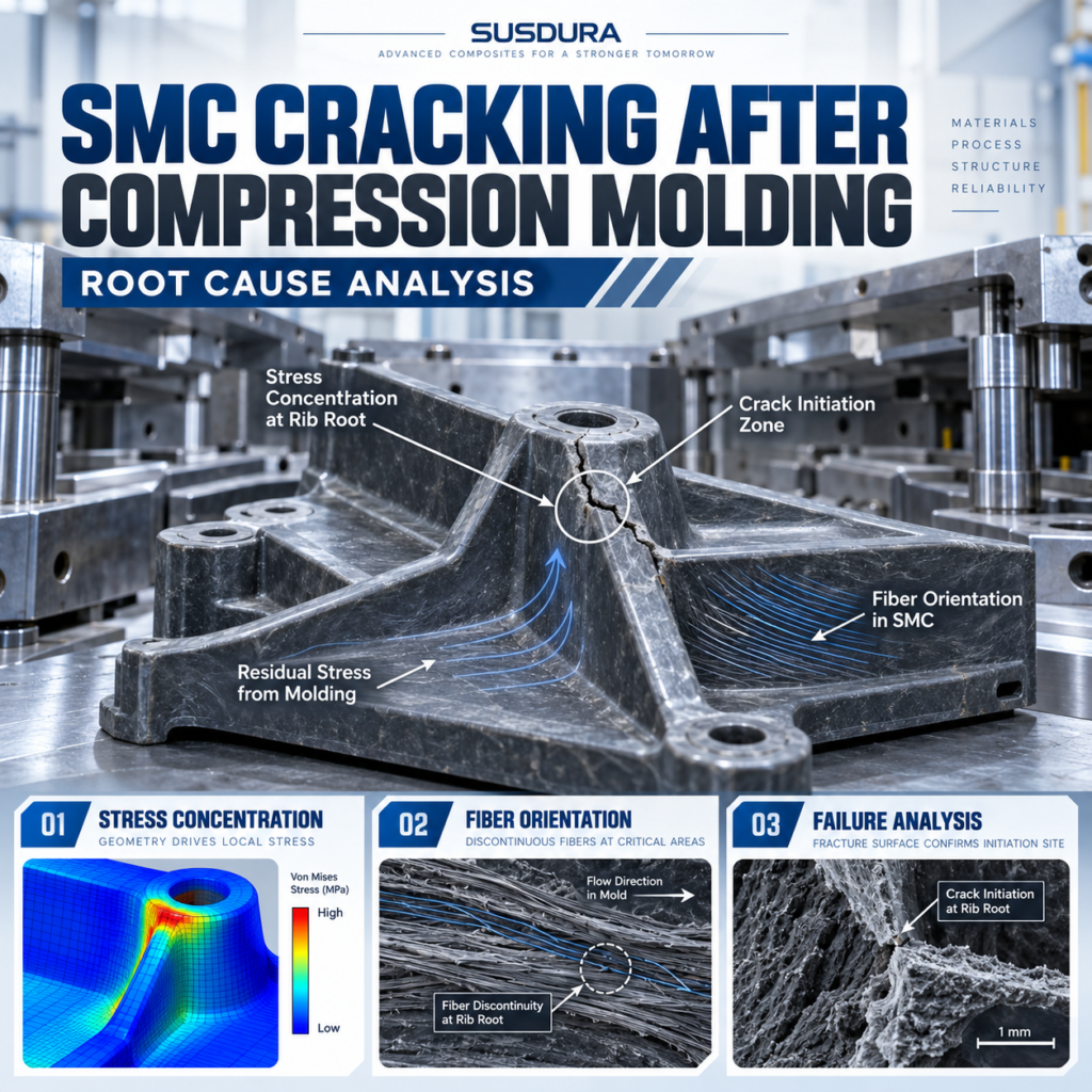
SMC cracking after compression molding can compromise structural strength, electrical insulation and product reliability, even when standard material tests meet specifications. For manufacturers facing SMC molded parts cracking during demolding, assembly or service, identifying the real failure mechanism is essential. This engineering guide examines SMC cracking, common SMC compression molding defects and practical SMC crack failure analysis methods to help prevent repeated failures.
TL;DR: Key Engineering Findings
Crack location and timing matter. Cracks appearing during demolding may have different causes from fractures occurring during assembly or operation.
High tensile strength does not guarantee crack resistance. Resin toughness, glass fiber orientation, interface strength and component geometry also determine structural performance.
Material and tooling must be evaluated together. An acceptable SMC compound can still fail around ribs, mounting holes or metal inserts.
Root cause analysis requires evidence. Fracture inspection, manufacturing records and representative mechanical tests are more reliable than uncontrolled process adjustments.
Long-term prevention depends on validation. Material formulation, design for manufacturing, molding parameters and component-level load testing must support the intended application.
1. Identifying SMC Cracking: Crack Types, Locations and Failure Timing
The first step in investigating SMC cracking is determining exactly what failed, where the failure began and when the damage developed.
SMC is a discontinuous fiber-reinforced thermosetting composite. Its failure behavior differs from that of unreinforced plastics because the resin matrix, glass fibers and fiber–matrix interfaces all contribute to load transfer.
Cracking may occur in several recognizable forms.
Surface cracking consists of shallow fissures in the resin-rich surface. These may result from local strain, curing effects or environmental exposure, although visual inspection alone cannot confirm their origin.
Structural cracking extends into the load-bearing cross-section and can reduce the component’s mechanical capacity.
Insert-area cracking develops around metallic inserts, threaded connections or mounting holes where localized stresses may be concentrated.
Rib-root and corner cracking appears near abrupt changes in geometry, particularly where structural stiffness or material flow patterns vary.
Failure timing provides another diagnostic clue:
During compression molding or mold opening
Immediately after demolding
During cooling or storage
During fastening and assembly
During mechanical loading or long-term operation
For example, a crack appearing during screw tightening requires examination of assembly torque, insert geometry and the local stress state. It should not automatically be attributed to poor curing.
Similarly, cracking following demolding may involve ejection forces, pre-existing damage, residual stress or inadequate material strength.
A technically sound investigation must establish whether the crack initiated before or during the observed failure event.
2. How Cracks Initiate and Propagate in SMC Composites
Understanding the mechanisms behind SMC crack formation requires examining how its constituent materials respond to mechanical and thermal stresses.
In a typical SMC formulation, the thermosetting resin transfers loads between reinforcing fibers, while mineral fillers and additives influence processing and material properties.
Crack initiation can involve four interconnected mechanisms.
Matrix Cracking
When local tensile strain or stress exceeds the effective resistance of the resin matrix, microscopic cracks may develop.
These cracks can originate near voids, resin-rich regions or geometric discontinuities.
A formulation with high stiffness but limited fracture toughness may be particularly sensitive to concentrated loading.
Fiber–Matrix Debonding
Effective reinforcement depends on load transfer across the interface between glass fibers and the cured resin.
If interfacial bonding is insufficient, separation may occur under loading, changing the local stress distribution and promoting further damage.
Fiber Fracture
Glass fibers provide important reinforcement, but their contribution depends on fiber length, orientation, distribution and load direction.
When individual fibers become overloaded, they may fracture and contribute to progressive damage.
Inter-Bundle Damage
SMC contains discontinuous fiber bundles with heterogeneous spatial distributions.
Local separation between bundles, matrix cracking and void-related damage can interact as fracture develops.
Unlike conventional continuous-fiber laminates, SMC does not necessarily have clearly defined structural ply interfaces.
A simplified engineering interpretation is:
Cracking becomes likely when local loading exceeds the damage resistance of the material and component structure.
That local loading may combine external force with residual thermal stress, molding-induced stress and assembly preload.
This explains why identical compounds can perform differently in components with different geometries.
3. Eight Major Root Causes of SMC Cracking After Compression Molding
8 Causes of SMC Cracking
Select a cause to view its effect and solution.
Brittle Resin
Low fracture toughness
Optimize resin toughness
SMC cracking after compression molding rarely has one universally applicable explanation.
The investigation should consider material formulation, fiber reinforcement, tooling geometry, curing behavior and handling conditions.
1. Brittle Resin Formulation
A resin system optimized primarily for stiffness, dimensional stability or surface appearance may not provide sufficient resistance to localized fracture.
Resin chemistry and additive selection should be evaluated against the actual loading requirements.
2. Unfavorable Glass Fiber Orientation
SMC fiber orientation changes as material flows through the mold.
If reinforcing fibers are poorly aligned with critical load paths, localized tensile resistance may be reduced.
3. Weak Fiber–Matrix Interfaces
Incompatible material constituents, inadequate surface treatment or processing-related defects can affect interfacial load transfer.
Reduced interface integrity may contribute to crack initiation and propagation.
4. Residual Thermal and Curing Stresses
Chemical curing shrinkage and cooling contraction can create internal stresses.
These stresses may add to externally applied loads, especially near constrained inserts or abrupt wall transitions.
5. Improper Charge Placement
Unbalanced charge distribution can produce excessive flow distances, localized fiber redistribution or poorly consolidated regions.
Flow-convergence areas deserve special attention where mechanical loads are concentrated.
6. Inadequate Curing Conditions
Insufficient or inconsistent curing can influence matrix properties, dimensional stability and load-bearing performance.
However, increasing mold temperature or curing time without validation may introduce additional processing problems.
7. Poor Component and Mold Design
Sharp internal corners, inadequate radii, thin sections beside thick bosses and unsupported load paths can increase local stress concentration.
8. Excessive Demolding or Assembly Loads
Ejection forces, forced removal, improper fixture support and excessive fastening torque may damage otherwise acceptable components.
| Root Cause | Possible Failure Pattern | Primary Investigation |
|---|---|---|
| Brittle resin | Matrix-dominated fracture | Resin formulation and toughness |
| Fiber orientation | Directional cracking | Fiber distribution and flow |
| Weak interface | Fiber pull-out or debonding | Fracture-surface microscopy |
| Residual stress | Cracks near constrained areas | Cure and thermal history |
| Charge placement | Local weak regions | Charge pattern and consolidation |
| Cure inconsistency | Variable failure resistance | Cure-state assessment |
| Structural design | Rib, corner or hole cracks | CAD and local stress analysis |
| Assembly or ejection | Localized post-molding cracks | Force, torque and handling records |
Key Takeaways
Material, design and processing factors often interact.
Crack appearance alone cannot confirm the root cause.
Controlled investigation is necessary before changing SMC formulations or tooling.
4. Why Do SMC Parts Crack Around Ribs, Holes and Metal Inserts?
Complex geometry is one of the most important differences between laboratory test specimens and commercial SMC components.
Standard tensile specimens typically have relatively simple geometries. Actual electrical insulation frames, busbar supports and industrial structural components contain ribs, mounting holes, bosses and embedded metal inserts.
These features can create multiaxial loading conditions that differ significantly from simple uniaxial tensile testing.
Rib-Root Cracking
Reinforcing ribs improve stiffness but can introduce stress concentration where they join a main wall.
Sharp transitions, unfavorable fiber orientation and local consolidation defects may increase damage sensitivity.
Gradual thickness transitions and suitable radii can help distribute stress, subject to component-level validation.
Cracking Around Mounting Holes
When a bolt is tightened, the surrounding composite experiences contact pressure and local deformation.
External operating loads may add tension, bending or shear.
The resulting stress field depends on hole geometry, edge distance, material properties and fastening arrangements.
Cracking Around Metal Inserts
Metal inserts introduce local geometric discontinuities and material interfaces.
Differences in thermal expansion, geometric restraint and assembly forces may contribute to localized stresses.
Thread design, insert shape, surrounding wall thickness and torque requirements should therefore be considered together.
For example, a component may pass a standardized tensile test but crack when a metal insert is subjected to excessive installation torque.
This is not necessarily contradictory.
The standard test measures material behavior under specified conditions; the assembled component experiences a different stress state.
A reliable design must be validated using loads representative of the intended application.
5. How to Conduct an Effective SMC Crack Failure Analysis
A disciplined SMC crack failure analysis should connect physical evidence, processing history and mechanical behavior.
The goal is to identify a cause that can be verified, corrected and prevented from recurring.
Step 1: Document the Failure
Record fracture location, direction, appearance, production batch, timing and operating conditions.
Retain failed parts and acceptable reference samples.
Avoid destructive preparation before the fracture surfaces have been documented.
Step 2: Examine the Fracture Surface
Begin with visual inspection and optical microscopy.
Where appropriate, scanning electron microscopy can help reveal fiber pull-out, matrix fracture features, voids and interfacial separation.
Interpretation should consider the possibility of secondary damage produced after initial cracking.
Step 3: Review Manufacturing Records
Check material batch data, formulation consistency, sheet condition, charge placement, mold temperature, curing cycle and ejection conditions.
Look for correlations between changes in production conditions and failure occurrence.
Step 4: Evaluate the Actual Loading Conditions
Review mounting geometry, tightening torque, applied forces, temperature exposure and loading frequency.
Finite element analysis may help identify stress concentration zones, but its predictions depend on realistic boundary conditions and suitable material properties.
Step 5: Conduct Comparative Mechanical Testing
Applicable standardized methods include:
ISO 527-4:2023: Tensile properties of specified fiber-reinforced plastic composites.
ISO 14125:1998: Flexural properties of fiber-reinforced plastic composites, including its applicable amendment.
These tests support material characterization but do not substitute for finished-component qualification.
Step 6: Confirm the Root Cause
Compare acceptable and failed parts, conduct controlled molding trials and verify proposed corrective actions.
The most convincing result is a reproducible connection between a suspected variable, the failure mechanism and the observed improvement.
6. Engineering Solutions to Prevent SMC Cracking
Effective SMC cracking prevention requires selecting corrective actions based on the verified failure mechanism.
Replacing the material with a higher-strength grade is not always the most effective solution.
A. Improve Material Formulation
Resin toughness, glass fiber length, reinforcement content, filler loading and interfacial compatibility should be selected according to the component’s loading requirements.
A higher glass fiber percentage may improve certain mechanical properties while introducing changes in flow behavior, anisotropy or local fracture response.
Material optimization should therefore evaluate strength, stiffness and fracture resistance separately.
B. Improve Part and Mold Design
Suitable corner radii, smoother wall transitions and reinforced load paths can reduce localized stress concentration.
Mounting holes and metal inserts should be designed for the expected combination of assembly and service loads.
Where appropriate, structural simulation can guide design adjustments before tooling changes.
C. Optimize Compression Molding
Charge placement and molding conditions should promote consistent consolidation and reinforcement distribution.
Mold temperature, pressure, closing behavior and cure time must be controlled within a validated operating window.
Particular attention should be given to complex ribs, bosses and flow-convergence regions.
D. Control Demolding and Assembly
Proper ejection support, controlled handling and validated assembly torque reduce avoidable mechanical damage.
Finished components should not be forced into alignment when unacceptable distortion or interference exists.
E. Validate Production Improvements
Corrective actions must be verified through representative specimens, actual component tests and repeatable production trials.
| Engineering Area | Possible Improvement | Validation |
|---|---|---|
| Material | Optimize toughness and reinforcement | Mechanical testing |
| Tooling | Improve radii and local geometry | Design and part testing |
| Molding | Control charge and curing | Production trials |
| Assembly | Control torque and support | Assembly load testing |
| Quality | Monitor critical characteristics | Inspection and traceability |
7. Engineering Case Study: Structural Reliability in Precision SMC Circuit Breaker Frames
A relevant example from SUSDURA’s manufacturing experience is the production of precision SMC insulating frames for air circuit breaker (ACB) assemblies.
Project Background
ACB insulation frames perform electrical insulation and structural support functions within circuit breaker mechanisms.
These components may include mounting interfaces, reinforcement ribs and complex molded features. Their operating environment can involve mechanical forces generated during switching operations, assembly stresses and temperature changes.
Engineering Challenge
For these components, the engineering objective is to achieve dimensional consistency while maintaining mechanical integrity and electrical insulation performance.
Potential cracking risks include local stress concentrations around mounting interfaces, rib roots and abrupt geometry transitions.
The challenge is not simply obtaining acceptable tensile strength from the selected SMC compound.
The complete molded structure must withstand the loads specified by the equipment manufacturer.
SUSDURA’s Manufacturing Approach
SUSDURA’s precision ACB frame manufacturing integrates:
Material selection: Application-specific SMC formulation and reinforcement control.
Tooling engineering: Mold geometry development and dimensional compensation.
Compression molding: Standardized operating parameters and production procedures.
Quality verification: CMM inspection and critical-dimension monitoring.
SUSDURA has previously reported a Cpk value of approximately 1.66 for a monitored dimensional characteristic associated with its precision ACB frame manufacturing.
This provides an example of dimensional process control, but Cpk does not independently establish fracture resistance.
Engineering Significance
This is an actual manufacturing and dimensional-control example rather than a documented case of successfully repairing previously cracked components.
Any specific claim regarding resistance to switching shock, fatigue or crack propagation requires corresponding mechanical verification.
The broader engineering lesson is that precision tooling, repeatable processing and material qualification provide an essential foundation for reliable SMC structural components.
8. How SUSDURA Controls Cracking Risks in Mass Production
Preventing SMC molded parts cracking requires consistent production control beyond initial prototype approval.
In commercial manufacturing, variations in compound preparation, molding conditions and component handling can influence mechanical performance.
SUSDURA combines material development, tooling manufacturing, compression molding and inspection to support repeatable component quality.
Material Consistency
Automated ingredient dosing and online X-ray SMC sheet-weight monitoring help maintain material production consistency.
Routine material testing and batch traceability support investigation when production variation occurs.
However, consistent sheet weight does not independently guarantee uniform fiber orientation or crack resistance.
Tooling and Process Control
In-house tooling development supports evaluation of component geometry, critical wall sections and ejection arrangements.
Standardized molding parameters help reduce uncontrolled changes in processing conditions.
Mechanical and Dimensional Validation
Material tensile and flexural testing provide useful mechanical property information.
For critical structural components, finished-part load testing may also be required to reflect actual loading conditions.
CMM inspection helps verify geometry, but acceptable dimensions alone do not guarantee mechanical integrity.
Continuous Quality Improvement
First-piece inspection, routine process checks, lot traceability and corrective-action reviews help identify deviations before they affect larger production volumes.
The objective is to establish a documented, repeatable manufacturing process in which material properties and finished-component performance remain within customer-approved requirements.
Frequently Asked Questions About SMC Cracking
1. Why do SMC parts crack after demolding?
SMC parts may crack after demolding due to residual curing stress, thermal contraction, excessive ejection forces or local structural weaknesses.
Cracks may also become visible after mold constraints are removed.
An effective investigation should examine fracture locations, material curing conditions, demolding procedures and the component’s geometric stress concentrations.
2. Does increasing glass fiber content prevent SMC cracking?
Not necessarily. Higher glass fiber content may improve certain mechanical properties, but crack resistance also depends on fiber length, orientation, resin toughness, interface quality and component geometry.
An inappropriate reinforcement level may affect material flow and create local performance variations.
The selected compound must be validated under representative loading conditions.
3. How can manufacturers prevent cracking around metal inserts in SMC parts?
Preventing insert-area cracking requires suitable insert geometry, surrounding wall thickness, load distribution and controlled assembly conditions.
Manufacturers should consider thermal expansion differences, molding shrinkage, stress concentration and fastening torque.
Finished-part testing is important when inserts transfer significant mechanical loads.
Conclusion: Preventing SMC Cracking Through Integrated Engineering
SMC cracking after compression molding is not necessarily the result of insufficient material strength. SMC molded parts cracking may involve brittle resin behavior, unfavorable fiber orientation, residual stresses, poor mold design, localized stress concentration or assembly loads.
Effective SMC crack failure analysis requires manufacturers to identify the actual fracture mechanism and validate corrective actions through engineering evidence.
Rather than treating SMC compression molding defects as isolated production problems, manufacturers should establish a comprehensive approach combining formulation development, tooling engineering, controlled processing and finished-component qualification.
For industrial applications requiring long-term structural integrity, SMC cracking prevention must begin during component design and continue through mass production.
Work With SUSDURA — Engineered SMC Materials and Precision Compression Molding
SUSDURA provides integrated manufacturing support for custom SMC materials, compression molds and precision molded composite components.
Our engineering capabilities include formulation development, tooling design, SMC compression molding, mechanical testing and dimensional inspection.
If your SMC components are experiencing cracking during demolding, assembly or operation, SUSDURA can evaluate the manufacturing and material requirements of your project.