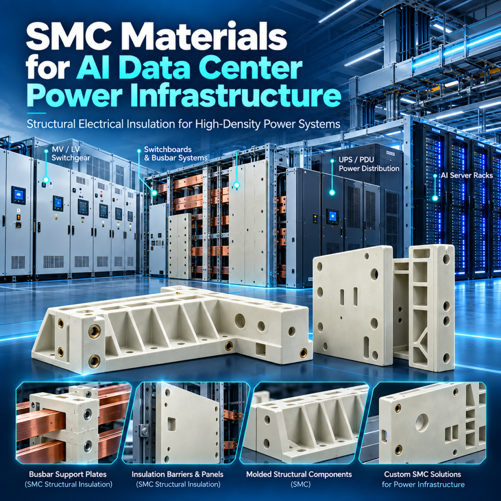
SMC materials for AI data center power infrastructure are becoming increasingly relevant as higher rack power density places greater electrical, mechanical and dimensional demands on switchgear, busways, UPS systems and power-distribution assemblies. For large molded insulation components, the challenge is no longer simply preventing electrical conduction. The component must often maintain insulation spacing, structural rigidity, dimensional accuracy and fire performance simultaneously.
TL;DR
- SMC is particularly relevant to large, structural and molded electrical insulation components, rather than small precision insulators.
- Potential applications include switchgear barriers, molded insulation walls, busbar support plates, structural panels and breaker insulation components.
- High CTI and dielectric strength matter, but mechanical strength, dimensional stability and molding consistency can be equally critical.
- Low-shrinkage SMC can help control flatness, hole position, insert location and assembly consistency.
- Emerging 800 VDC AI architectures increase the importance of insulation coordination and complete component-level validation.
Why High-Density AI Power Systems Need Structural Electrical Insulation
Electrical insulation inside conventional power equipment already performs more than one function, but high-density AI infrastructure makes this multifunctional role increasingly important.
AI racks are moving toward power levels measured in hundreds of kilowatts. Schneider Electric currently describes AI power-train architectures spanning approximately 142 kW to 1 MW per rack, while its 800 VDC materials specifically discuss racks exceeding 400 kW and moving toward the megawatt range.
As power density increases, equipment such as MV/LV switchgear, switchboards, UPS systems and busway assemblies must maintain reliable electrical separation while carrying greater power through increasingly compact spaces.
A structural insulation component may therefore have to perform several functions simultaneously:
Electrical isolation — maintaining separation between energized conductors and grounded structures.
Mechanical support — carrying loads from busbars, inserts or assembled equipment.
Dimensional positioning — maintaining conductor spacing, hole locations and mounting geometry.
Thermal stability — resisting distortion as operating temperatures change.
This is why a molded switchgear wall cannot be evaluated only by dielectric strength. If the component warps, moves an insert or alters busbar spacing, its functional reliability can be affected even if the base material still has strong electrical properties.
For AI data center equipment, the more useful question is therefore:
Can the insulation component maintain its electrical, mechanical and dimensional integrity throughout the intended service environment?
That is where structural thermoset composites such as SMC become relevant.
Key Takeaways
- Structural insulation performs electrical and mechanical functions simultaneously.
- Increasing power density makes dimensional control more important.
- Material performance must be evaluated together with component geometry.
Where SMC Can Be Used in AI Data Center Power Infrastructure
SMC should not be presented as a universal “data center material.” Its strongest potential lies in large structural electrical insulation components used inside the power equipment serving the data center.
| Power Equipment | Potential SMC Component | Primary Function |
|---|---|---|
| MV/LV Switchgear | Structural insulation parts | Electrical + structural |
| Switchboard | Insulation panels / barriers | Isolation + positioning |
| Busbar System | Large busbar support plates | Insulation + load support |
| Circuit Breaker Assembly | Structural molded insulation | Precision + mechanical |
| UPS Equipment | Molded structural components | Support + insulation |
| PDU | Large molded insulation parts | Electrical separation |
| Busway | Structural supports / separators | Positioning + insulation |
| Power Sidecar | Structural electrical components | Mechanical + electrical |
The distinction between SMC and BMC is important here.
SMC is especially attractive when the design requires a relatively large molded surface, reinforcing ribs, bosses, multiple mounting features or a component that must carry meaningful structural load.
Compact standoff insulators, small insert-molded supports and intricate precision components are often better candidates for BMC and should be treated separately.
In other words, the SMC opportunity is best defined as:
Large + Structural + Molded Electrical Insulation
rather than simply “electrical insulators.”
This distinction also helps engineering teams avoid choosing a material based only on the application name. Two components located in the same switchboard may require completely different reinforcement, molding flow and dimensional-control strategies.
Key Takeaways
- SMC is most relevant to larger structural insulation components.
- Switchgear, busbar assemblies and breaker structures are natural areas to evaluate.
- SMC and BMC should not be treated as interchangeable technologies.
Internal Link Suggestion: Explore SUSDURA SMC Electrical Insulation Components.
Why SMC Works as a Structural Electrical Insulation Platform
SMC is valuable not because it is simply “fiberglass plastic,” but because several parts of the material system can be engineered together.
The glass-fiber reinforcement contributes stiffness, strength and structural stability. Fiber content, fiber length, distribution and orientation all influence how the molded component carries load.
The thermoset resin system provides the continuous matrix and can be formulated around electrical, thermal, chemical and flame-performance objectives.
Compression molding then allows these material properties to be translated into relatively large and geometrically complex components containing features such as:
- Ribs
- Bosses
- Variable wall thickness
- Mounting holes
- Reinforced load paths
- Metal inserts
- Integrated structural geometry
This combination is especially useful for switchgear and power-distribution components that cannot be reduced to a simple flat insulating sheet.
The formulation itself can also be adapted around application-specific requirements. An electrical-grade SMC may prioritize a different balance of properties depending on whether the application demands high CTI, flame retardancy, low shrinkage, high mechanical strength, environmental resistance or dimensional stability.
The important word is balance.
Increasing one property can influence processing or another performance characteristic. Higher reinforcement may affect mold flow. Flame-retardant packages can influence physical properties. Low-shrink systems may change molding behavior.
For this reason, SMC is best regarded as:
A configurable structural electrical insulation platform.
Material formulation, part geometry and molding process should be developed together.
Key Takeaways
- SMC performance comes from the combination of reinforcement, resin and molding.
- Formulation can be adjusted for different electrical and mechanical requirements.
- Maximizing one property does not automatically create the best component.
Internal Link Suggestion: Learn more about Custom SMC Material Development.
Six Critical SMC Properties for AI Data Center Power Equipment
A useful SMC electrical insulation material specification should cover more than dielectric strength.
| Requirement | Relevant SMC Property | Typical Evaluation |
|---|---|---|
| Electrical isolation | Dielectric strength / IR | IEC 60243 / OEM specification |
| Surface tracking | CTI / PTI | IEC 60112 |
| Fire performance | Flame retardancy | UL 94 / equipment specification |
| Structural support | Tensile / flexural / compression | Mechanical testing |
| Dimensional accuracy | Shrinkage / warpage | CMM / dimensional inspection |
| Environmental durability | Heat / humidity / aging | Environmental testing |
CTI and Tracking Resistance
IEC 60112:2025 specifies methods for determining the proof and comparative tracking indices of solid insulating materials using AC voltage. CTI is useful for material characterization and comparison, but it is not a stand-alone definition of insulation-system safety.
IEC 60112:2025 — Official IEC Standard
A higher CTI value should therefore not be translated automatically into a specific safe creepage distance without considering the applicable equipment standard, pollution degree and insulation coordination.
Dielectric Performance
IEC 60243-1 provides test methods for determining short-time electric strength of solid insulating materials at power frequencies.
IEC 60243-1 — Electric Strength of Insulating Materials
Thickness, conditioning, temperature and environmental exposure all matter when interpreting results.
Flame Retardancy
UL 94 classifications such as V-0, V-1 and V-2 describe small-scale flammability behavior under defined test conditions. UL explicitly treats these classifications as material/component test data, not as proof that an entire assembly automatically meets all applicable fire requirements.
UL Solutions — Combustion and Fire Tests for Plastics
Mechanical, Dimensional and Environmental Performance
For structural SMC, tensile strength, flexural performance, insert retention, warpage, moisture resistance and heat aging can be just as important as electrical test values.
Key Takeaways
- SMC qualification requires a property matrix, not one headline value.
- CTI and dielectric strength must be interpreted within the complete insulation design.
- Mechanical and dimensional properties are essential for structural applications.
Internal Link Suggestion: Learn more about High-CTI and Flame-Retardant SMC Materials.
SMC for Switchgear and Busbar Structural Insulation
Switchgear is one of the strongest potential application areas for structural SMC because electrical performance and dimensional accuracy are closely connected.
Possible molded components include:
Insulation walls
Arc barriers
Side plates
Structural panels
Breaker frames
Busbar support plates
Molded support structures
Consider an insulation wall separating conductors inside a switchboard. Its job is not finished once the resin has sufficient dielectric strength.
The molded component may also define:
- Busbar spacing
- Insert position
- Hole spacing
- Breaker alignment
- Mechanical mounting points
- Clearances to adjacent structures
If the part develops excessive warpage, the result may be assembly interference, displaced inserts or altered conductor positioning.
This is why SMC for data center switchgear should be treated as a structural engineering material rather than just an electrical plastic.
The same principle applies to large SMC busbar support plates.
During normal operation they maintain conductor position. During abnormal or short-circuit conditions, however, the support system may also be subjected to significant electromagnetic loading. The required component therefore combines two design problems:
Electrical insulation + mechanical structural support
For larger multi-busbar systems, stiffness, tensile and flexural performance, insert retention and fracture resistance can all influence the design.
The actual load case must be determined by the equipment manufacturer. The material should then be qualified together with the final support geometry rather than by relying only on coupon data.
Key Takeaways
- Switchgear insulation is highly sensitive to geometry and dimensional consistency.
- Large busbar supports combine insulation and structural-load requirements.
- Final component testing is more meaningful than material data alone.
Why Low-Shrinkage SMC Matters for Electrical Power Equipment
Low shrinkage is often discussed as a surface-quality or appearance issue. For structural electrical components, however, its importance is much more functional.
Consider the geometric requirements of a large molded switchgear component:
Insert position
Hole spacing
Flatness
Parallelism
Wall thickness
Mounting accuracy
Busbar spacing
If material shrinkage varies from part to part, these dimensions can move.
That creates a chain of consequences:
Material shrinkage variation
↓
Component dimensional variation
↓
Assembly deviation
↓
Possible change in conductor positioning or designed spacing
For this reason, low-shrinkage SMC can be highly relevant to power-distribution components where precise geometry must be repeated over high production volumes.
Achieving dimensional stability requires more than adding a low-profile additive.
The complete control strategy may involve:
- Resin formulation
- Low-shrink / low-profile system
- Controlled glass-fiber distribution
- Stable SMC sheet weight
- Material maturation
- Charge pattern
- Tool temperature
- Compression pressure
- Cure behavior
- Mold compensation
- Post-molding dimensional verification
This leads to an important engineering principle:
Dimensional stability is a system capability, not simply a datasheet property.
An SMC formulation with nominally low shrinkage can still produce inconsistent components if sheet weight, fiber distribution, tooling or molding parameters are poorly controlled.
For AI power infrastructure, where compact equipment layouts increase the importance of predictable component geometry, this becomes especially relevant.
High-Strength SMC for Mechanical Loads and Fault Conditions
Electrical insulation components are sometimes incorrectly treated as mechanically passive parts.
In reality, structural insulation may experience:
Assembly force
Bolt preload
Insert pull-out load
Bending load
Compression
Vibration
Thermal expansion
Short-circuit electrodynamic force
This is particularly relevant to busbar supports, breaker structures and large structural partitions.
A high-strength SMC formulation therefore has to balance multiple variables.
Glass-fiber content is important, but simply increasing glass content does not automatically produce the best component.
Mechanical performance also depends on:
Fiber length — longer reinforcement can improve load transfer but may make molding more demanding.
Fiber orientation — molding flow changes local reinforcement direction.
Fiber distribution — local fiber-rich and resin-rich areas can affect repeatability.
Resin system — matrix toughness and bonding influence fracture behavior.
Fiber/matrix interface — efficient stress transfer is essential.
Part geometry — ribs, corners, holes and inserts create local stress concentrations.
Molding parameters — pressure, temperature and charge placement affect final structure.
Consequently:
More glass fiber does not automatically mean a better electrical structural component.
The correct formulation should be developed around the actual loading mode and molded geometry.
For busbar support systems, component-level load testing is particularly valuable because it captures geometry, metal inserts, molding direction and local stress concentrations that a simple material coupon cannot reproduce.
Key Takeaways
- Structural insulation can experience substantial mechanical loads.
- Glass content is only one part of SMC mechanical design.
- Component-level validation is essential for highly loaded supports.
What 800 VDC Means for SMC Electrical Insulation Design
The move toward 800 VDC is one of the most important current developments in AI data-center power architecture.
NVIDIA stated in August 2026 that its 800 VDC architecture is intended to reduce power-conversion stages and support denser accelerated-computing systems. NVIDIA, Google and Microsoft have also collaborated through the Open Compute Project on 800 VDC architecture specifications, while an ecosystem of equipment manufacturers is developing compatible hardware.
Schneider Electric similarly identifies 800 VDC as an architecture for racks exceeding roughly 400 kW and moving toward 1 MW.
For SMC manufacturers, however, the correct conclusion is not:
“High-CTI SMC is automatically suitable for 800 VDC.”
Instead, an SMC component intended for higher-voltage DC equipment needs to be evaluated within the complete insulation system.
Relevant factors can include:
- CTI
- Creepage
- Clearance
- Dielectric strength
- DC electric stress
- Surface geometry
- Ribs and barriers
- Metal inserts
- Contamination
- Operating temperature
- Environmental conditioning
- Protection architecture
A material can have excellent dielectric properties while the component design still creates an unsuitable electrical field or insufficient spacing.
Therefore:
A material datasheet alone cannot qualify an SMC component for an 800 VDC system.
Material selection must be combined with system design, the relevant equipment standards and final component validation.
Key Takeaways
- 800 VDC increases the importance of complete insulation-system design.
- CTI alone cannot qualify an SMC component for higher-voltage DC service.
- Geometry and equipment-level validation remain essential.
How to Select an SMC Grade for AI Data Center Electrical Equipment
Purchasing an electrical-grade SMC should not begin with the question:
“Do you have data center SMC?”
“Data center” describes an industry environment, not a complete material specification.
A useful RFQ should define the actual component and operating conditions.
| Parameter | Customer Should Provide |
|---|---|
| Component Type | Panel / barrier / support / frame |
| Application | Switchgear / UPS / busway / PDU |
| Rated Voltage | AC / DC |
| CTI Requirement | OEM or project specification |
| Dielectric Requirement | Test method and target |
| Flame Requirement | UL 94 / OEM requirement |
| Mechanical Load | Tensile / flexural / compression |
| Maximum Temperature | Continuous / peak |
| Geometry | Overall dimensions |
| Wall Thickness | Nominal / critical areas |
| Inserts | Material / thread / location |
| Dimensional Tolerance | Critical dimensions |
| Environment | Humidity / chemicals / contamination |
| Production Volume | Prototype / annual demand |
This information allows the material supplier to balance formulation, reinforcement and molding behavior around the actual application.
A high-CTI formulation, for example, may still need adjustment if the molded part has unusually long flow distances. A high-strength formulation may need optimization around insert areas. A low-shrink system must still meet flame, electrical and mechanical requirements.
The correct engineering sequence is therefore:
Application → Requirements → Material → Tooling → Process → Validation
not:
Generic SMC grade → hope it works
Key Takeaways
- “Data center SMC” is not a sufficient technical specification.
- A proper RFQ should include electrical, mechanical, geometric and environmental data.
- Material development should begin from the component requirements.
FAQ
1. What SMC materials are suitable for AI data center power equipment?
There is no single universal “AI data center SMC.” The required SMC formulation depends on the component. Electrical-grade formulations may need combinations of high CTI, dielectric performance, flame retardancy, mechanical strength, low shrinkage, dimensional stability or environmental resistance. Material selection should begin with the specific switchgear, busbar, UPS or power-distribution component requirements.
2. Is SMC suitable for busbar support applications?
SMC can be suitable for larger structural busbar support plates and molded support structures where electrical insulation, stiffness, mechanical strength and dimensional stability are required together. Compact standoff-type supports may instead be better suited to BMC. Final suitability depends on busbar geometry, voltage, fault loading, inserts, spacing and component-level validation.
3. Can SMC be used in 800 VDC power equipment?
Potentially, but suitability cannot be determined from CTI or dielectric strength alone. The SMC formulation, component geometry, creepage, clearance, metal inserts, environmental conditions, insulation coordination and applicable equipment standards must all be evaluated. A material grade should not be described as “800 VDC qualified” solely from datasheet values.
Conclusion: SMC as Structural Electrical Insulation for AI Power Infrastructure
As AI data center power systems become denser, larger molded insulation components must increasingly combine electrical insulation with mechanical strength, dimensional precision and long-term environmental stability.
For this reason, SMC materials for AI data center power infrastructure are best evaluated not simply as insulating plastics, but as structural electrical engineering materials.
Potential applications range from switchgear insulation walls and structural barriers to breaker components and large busbar support plates. In each case, the formulation must balance electrical properties with reinforcement, molding flow, dimensional stability, flame performance and environmental requirements.
SUSDURA develops electrical-grade SMC, high-CTI SMC, flame-retardant SMC, low-shrinkage SMC and high-strength SMC for demanding electrical applications. By combining material formulation, SMC sheet manufacturing, in-house tooling, compression molding and validation, SUSDURA can support electrical OEMs from material development through qualified production components.