Electrical insulation materials for AI data centers are becoming increasingly important as GPU-intensive computing pushes more electrical power into smaller physical spaces. Higher rack power density creates new demands for switchgear, busways, UPS systems, busbar supports and power distribution equipment. For electrical OEMs, the challenge is no longer simply insulation—it is maintaining electrical, mechanical, thermal and dimensional reliability at the same time.
TL;DR
- AI data centers are driving much higher rack power density, increasing the importance of reliable AI data center power distribution and electrical insulation.
- SMC is well suited to larger structural insulation parts, barriers, panels and molded switchgear components, while BMC is particularly effective for compact insulators, busbar supports and insert-molded components.
- CTI, dielectric performance, flame retardancy, mechanical strength, dimensional stability and environmental resistance should be considered together rather than independently.
- Emerging 800 VDC data center architectures make insulation coordination, creepage, clearance and DC-system design increasingly important.
- Material qualification should be based on the actual electrical component, geometry, operating environment and OEM specification—not on a single material data-sheet value.
Why AI Data Centers Are Changing Power Distribution Architecture
Traditional data centers were generally designed around power densities far below those now associated with large GPU clusters. AI workloads concentrate far more computing capacity into each rack, which means substantially more electrical power must be delivered through the same—or even smaller—physical footprint.
Schneider Electric reported in July 2026 that average rack density had increased from approximately 16 kW in 2025 to 27 kW in 2026, while some of the newest AI systems can reach approximately 246 kW per rack. Other next-generation architectures are being developed for still higher densities.
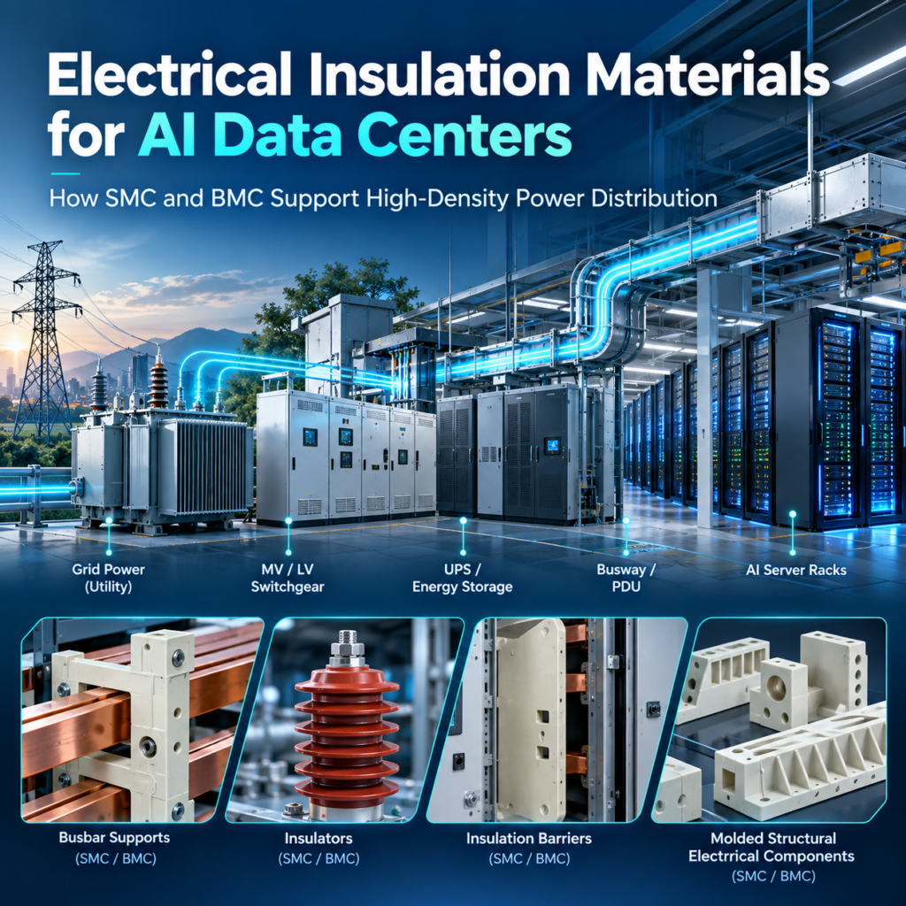
This changes the complete AI data center power infrastructure:
Utility / On-Site Power → Transformer → MV Switchgear → LV Distribution → UPS / Energy Storage → PDU / Busway → Rack Power Distribution → AI Rack
As rack density rises, electrical designers must manage not only higher total power, but also higher current concentration, heat generation, fault energy, physical conductor size and space constraints.
The industry is therefore examining higher-voltage distribution architectures. NVIDIA, Schneider Electric and Eaton are among the companies developing or supporting 800 VDC architectures intended to reduce conversion stages and enable higher-density power delivery.
For insulation-component manufacturers, this shift matters because electrical insulation becomes part of a larger system-level challenge involving electrical performance, thermal management, mechanical support and long-term reliability.
Key Takeaways
- AI computing is turning data-center design into a power-distribution challenge.
- Higher rack density increases pressure on switchgear, busway, UPS and insulation systems.
- Electrical insulation should be evaluated as part of the complete power architecture.
Internal Link Suggestion: Learn more about SMC materials for electrical power distribution equipment.
Where Electrical Insulation Materials Are Used in AI Data Center Power Infrastructure
SMC and BMC should not be described as “AI data center materials” in isolation. They are electrical insulation materials used in power equipment that may form part of data center electrical infrastructure.
Their potential applications extend across multiple stages of the power chain.
| Power Infrastructure | Potential Insulation Components | Important Requirements |
|---|---|---|
| MV/LV Switchgear | Insulation barriers, structural supports, molded insulation parts | CTI, dielectric performance, flame resistance |
| Switchboards | Busbar supports, insulating plates, barriers | Mechanical and electrical performance |
| UPS Systems | Busbar insulators, molded support components | Thermal and electrical stability |
| PDU | Standoff insulators, terminal insulation | Precision, CTI, dimensional stability |
| Busway | Busbar supports, separators, insulating supports | Mechanical strength and insulation |
| Power Sidecar | Structural insulating components | Electrical, mechanical and thermal performance |
| Rack Power Distribution | Insulators and support components | Compact geometry and reliability |
Actual material use depends on the OEM architecture, rated voltage, current, creepage and clearance requirements, certification strategy and mechanical design. A busbar support used in a low-voltage switchboard, for example, cannot automatically be transferred into an 800 VDC system simply because the base material has adequate dielectric strength.
The correct question is therefore not, “Can SMC or BMC be used in a data center?” but rather:
What electrical, mechanical and environmental requirements must the specific molded insulation component satisfy?
That approach leads to much more reliable material selection.
Key Takeaways
- SMC/BMC applications exist primarily inside electrical power equipment.
- Application requirements vary significantly between switchgear, UPS, PDU and busway systems.
- Material qualification must be component- and system-specific.
Internal Link Suggestion: Explore SUSDURA electrical insulation components for switchgear and power distribution.
SMC vs. BMC: Different Roles in Data Center Electrical Equipment
Although SMC and BMC are both thermoset composite molding compounds, they should not be treated as interchangeable.
SMC electrical insulation material is particularly attractive where the design involves larger surface areas, structural loading, panels, barriers or relatively large molded components. Its reinforcement architecture can support high mechanical performance while allowing manufacturers to produce complex structural insulation parts through compression molding.
Potential applications include large switchgear insulation components, structural barriers, busbar support plates, breaker insulation structures and cabinet-related molded parts.
BMC electrical insulation material, by contrast, is highly suitable for smaller, more geometrically complex components, especially where metal inserts, threads, controlled dimensions and high-volume molding are required. Typical examples include BMC busbar supports, standoff insulators, switchgear insulators and terminal-support components.
| Requirement / Component | SMC | BMC |
|---|---|---|
| Large structural insulation component | Excellent | Limited |
| Large insulation panel / barrier | Excellent | Less suitable |
| Busbar support plate | Excellent | Good |
| Compact busbar insulator | Good | Excellent |
| Standoff insulator | Possible | Excellent |
| Complex geometry | Good | Excellent |
| Metal insert molding | Good | Excellent |
| High-volume precision component | Good | Excellent |
| Large switchgear molded component | Excellent | Good |
| Low-shrink dimensional control | Excellent | Excellent |
The final choice should consider geometry, reinforcement requirements, molding flow, insert configuration, tolerance, production volume and electrical specification together.
Key Takeaways
- SMC is particularly strong for larger structural electrical insulation parts.
- BMC is highly effective for compact, precision and insert-molded components.
- Material selection should begin with component geometry and functional loading.
Internal Link Suggestion: Learn more about BMC materials for electrical insulators and busbar supports.
Six Critical Material Requirements for High-Density Power Distribution
Material specifications for high-density power distribution should extend beyond a generic requirement such as “high insulation.” Six performance areas deserve particular attention.
1. Electrical Insulation
Dielectric strength and insulation resistance are fundamental, but test values must correspond to the actual thickness, conditioning and application requirements.
2. Tracking Resistance
CTI is frequently used to compare the tracking resistance of insulating materials. The current IEC reference is IEC 60112:2025, which specifies methods for determining proof and comparative tracking indices of solid insulating materials. Importantly, IEC notes that CTI results should not by themselves be used to determine safe creepage distances in electrical apparatus.
IEC 60112:2025 – Official IEC Standard
3. Flame Retardancy
Depending on the equipment and approval strategy, materials may require a defined flammability classification. UL 94 includes classifications such as HB, V-2, V-1 and V-0. However, a UL 94 V-0 material rating does not mean the complete component or electrical assembly automatically satisfies every applicable fire-safety requirement.
UL Solutions – Standards for Evaluating Plastic Products
4. Mechanical Strength
Busbar supports can experience structural loads during assembly, service and fault conditions. Tensile, flexural and insert-retention performance may therefore be as important as electrical insulation.
5. Thermal and Dimensional Stability
Shrinkage, warpage, insert position and dimensional drift can affect insulation spacing and assembly accuracy.
6. Environmental Resistance
Humidity, contamination, temperature cycling and long-term aging should be considered according to the actual equipment environment.
Key Takeaways
- No single material property defines electrical-insulation performance.
- CTI should support—not replace—proper insulation coordination.
- Electrical, fire, mechanical and dimensional properties must be evaluated together.
Internal Link Suggestion: Learn more about high-CTI and flame-retardant SMC/BMC materials.
Why Busbar Supports Matter More as Power Density Increases
Busbars are increasingly important in high-capacity electrical distribution because they provide an efficient method of carrying substantial current through switchboards, UPS systems, PDUs, busways and other power equipment.
The insulation component supporting a busbar performs two fundamentally different functions.
First, it provides electrical isolation between energized conductors and other conductive structures.
Second, it acts as a mechanical structural component, maintaining conductor position under assembly loads, thermal expansion and electromagnetic forces.
Under short-circuit conditions, the forces acting between conductors can increase significantly. This means a busbar support cannot be evaluated only by CTI or dielectric strength. Mechanical characteristics such as tensile strength, flexural strength, insert retention, compressive capability and fracture behavior can be equally important.
A properly engineered busbar support insulator may therefore require a performance matrix covering:
CTI + dielectric performance + insulation resistance + mechanical strength + flame retardancy + dimensional stability + environmental durability
BMC can be particularly attractive for compact molded busbar supports because complex geometries and threaded metal inserts can be integrated during molding. SMC may be more appropriate for larger busbar support plates or structural insulating members.
For AI data center equipment, the exact material and support geometry should still be validated against the equipment manufacturer’s fault-current, voltage, spacing and mechanical requirements.
Key Takeaways
- Busbar supports perform both electrical and structural functions.
- Fault conditions make mechanical strength an important design consideration.
- BMC and SMC can address different busbar-support geometries and load cases.
800 VDC AI Data Centers: What Changes for Electrical Insulation?
The emergence of 800 VDC data center architecture is one of the most important developments in AI power infrastructure.
NVIDIA described in August 2026 how its 800 VDC architecture is intended to reduce conversion stages between the grid and accelerator while supporting much denser compute systems. The company also said NVIDIA, Google and Microsoft have worked through the Open Compute Project on 800 VDC specifications, with a broader equipment ecosystem developing around the architecture.
Schneider Electric likewise describes 800 VDC as an architecture for AI racks moving into the hundreds-of-kilowatts range and toward megawatt-class systems.
For electrical-insulation engineers, however, “higher voltage” does not simply mean “choose a material with a higher dielectric-strength number.”
An 800 VDC system requires consideration of:
- Creepage distance
- Clearance
- Insulation coordination
- Tracking resistance
- Surface contamination
- DC arc behavior
- Thermal environment
- Conductor geometry
- Protection strategy
- Fault conditions
CTI remains useful when comparing material tracking behavior, but it is only one input into a broader insulation design.
The component geometry also matters. Sharp edges, metal inserts, fastening systems, rib design, molded surfaces and nearby conductors can all affect electrical field distribution and effective insulation spacing.
For this reason, SMC or BMC proposed for future 800 VDC equipment should be qualified at the component and system level rather than selected solely from a compound data sheet.
Key Takeaways
- 800 VDC is becoming an important architecture for next-generation AI power delivery.
- Insulation coordination becomes more complex as voltage and power density increase.
- Material data must be combined with geometry, spacing and system-level validation.
Liquid Cooling Changes the Environment Around Power Equipment
High-density AI computing has also accelerated adoption of liquid cooling.
This does not mean SMC or BMC should automatically be marketed as “liquid-cooling materials.” Their more relevant role is in electrical equipment that may operate increasingly close to coolant distribution infrastructure.
Schneider Electric notes that power and cooling requirements are becoming increasingly interconnected as AI rack densities rise, while Eaton similarly states that power and cooling decisions at extreme rack densities need to be considered together.
For insulation-component engineers, this creates additional environmental questions:
What happens if humidity rises?
Could condensation occur under an abnormal condition?
What fluids are present in nearby systems?
Could maintenance or leakage expose the component to coolant or cleaning chemicals?
Does insulation resistance remain stable after environmental conditioning?
The answers cannot be generalized across every data center. Different cooling technologies, coolant chemistries, equipment layouts and containment strategies create different exposure conditions.
Material evaluation may therefore include humidity aging, water absorption, insulation resistance after conditioning, chemical exposure, thermal cycling and dimensional inspection.
For thermoset composite components, moisture resistance and dimensional stability can become important supporting characteristics, but they should be validated using conditions that reflect the real equipment environment.
How to Select SMC/BMC Materials for Data Center Electrical Equipment
A reliable material-development program should begin with the component specification rather than with a standard SMC or BMC grade.
Before selecting a formulation, engineers should define the complete operating envelope.
| Category | Information Required |
|---|---|
| Application | Switchgear / UPS / PDU / Busway / Other |
| Rated Voltage | AC or DC operating voltage |
| Electrical Requirements | Dielectric strength / IR / CTI |
| Flame Requirement | UL 94 or specific OEM requirement |
| Mechanical Load | Tensile / flexural / compression / fault load |
| Temperature | Continuous and short-term limits |
| Environment | Humidity / contamination / chemical exposure |
| Geometry | Dimensions / thickness / ribs / creepage geometry |
| Metal Inserts | Brass / steel / threaded insert |
| Dimensional Requirement | Critical tolerances / flatness / insert location |
| Production Volume | Prototype / pilot / annual demand |
| Approval Requirements | IEC / UL / OEM-specific specification |
This information allows material formulation and component design to be developed together.
For example, increasing glass-fiber content may improve certain mechanical properties but can also affect flow behavior and surface quality. Adding flame-retardant systems can influence molding characteristics and other properties. Low-shrink formulations may improve dimensional accuracy, but they must still satisfy electrical and mechanical requirements.
The objective is therefore not to maximize one property. It is to create a balanced material system capable of meeting the complete component specification with repeatable manufacturing performance.
Key Takeaways
- Start with the application specification, not the material grade.
- Electrical, mechanical, thermal and molding requirements interact.
- The best formulation is usually a balanced engineering compromise.
From Material Formulation to Molded Electrical Component
For critical electrical insulation components, material formulation is only the beginning.
SUSDURA integrates the development process across:
Material Formulation → Tooling → Compression Molding / BMC Injection → Insert Molding → Electrical Testing → Mechanical Testing → Dimensional Validation → Production Control
This integrated approach allows engineering teams to evaluate whether a material that performs well in a laboratory can also produce a stable commercial component.
For electrical applications, relevant verification capabilities can include CTI, dielectric performance, insulation resistance and flame-related testing together with mechanical strength and dimensional inspection.
Tooling and molding control are equally important. A material with excellent laboratory properties can still produce an unreliable component if molding generates excessive warpage, inconsistent fiber distribution, poor insert position or dimensional variation.
Production consistency therefore requires control from raw material through the finished molded component.
For SMC manufacturing, SUSDURA uses controlled material preparation and online sheet-weight monitoring to support compound consistency. For molded components, dimensional validation, process control and batch traceability can then be integrated into production.
This is particularly relevant when developing data center switchgear insulation, busbar supports and other components where electrical performance must coexist with precise geometry and mechanical loading.
The objective is a complete engineering chain:
Material + Mold + Component + Validation
rather than simply supplying a generic molding compound.
Key Takeaways
- Good material performance does not automatically guarantee a good molded component.
- Tooling, molding parameters, inserts and dimensional control affect final performance.
- Integrated material-to-component development can reduce qualification risk.
FAQ
1. Are SMC and BMC used in AI data center electrical equipment?
SMC and BMC can be considered for electrical insulation components used in equipment such as switchgear, switchboards, UPS systems, PDUs and busway assemblies. Their suitability depends on the specific component design, voltage, mechanical loading, thermal environment, certification requirements and OEM specification.
2. What is the difference between SMC and BMC for electrical insulation?
SMC is generally better suited to larger structural molded components, panels, barriers and support plates. BMC is particularly suitable for smaller precision components, complex geometries, standoff insulators and components requiring integrated metal inserts. Both materials can be formulated for electrical insulation, tracking resistance, flame retardancy and dimensional stability.
3. Is CTI enough to select an insulation material for an 800 VDC system?
No. CTI is useful for comparing tracking resistance, but insulation design must also consider creepage, clearance, dielectric performance, contamination, component geometry, environmental conditions and the applicable equipment standard. IEC 60112 itself notes that CTI test results should not be used directly to determine safe creepage distances.
Conclusion: Engineering Electrical Insulation for the Next Generation of AI Power Infrastructure
As AI computing pushes rack power density higher, electrical insulation materials for AI data centers will need to support increasingly demanding combinations of electrical, mechanical, thermal and environmental performance.
SMC and BMC can provide valuable engineering options for AI data center power distribution, including switchgear insulation, busbar support systems, standoff insulators, structural insulation components and other molded electrical parts. However, successful application depends on selecting the correct formulation and validating it against the real operating conditions of the component.
SUSDURA develops customized SMC electrical insulation material, BMC electrical insulation material, high-CTI formulations, flame-retardant compounds, low-shrinkage materials and high-strength molded electrical components. By integrating material formulation, tooling, molding and testing, SUSDURA can support OEMs developing electrical infrastructure for increasingly high-density power applications.