For electrical busbar supports, passing flame, dielectric and insulation tests is only part of the challenge. When the finished component must resist severe tensile loading without cracking around fasteners or losing structural integrity, conventional electrical SMC may not provide enough mechanical margin. SUSDURA developed High Strength SMC using long glass fiber reinforcement to address precisely this type of high-load electrical application.
TL;DR
- A customer required a finished busbar support assembly to withstand FH1 ≥ 1960 daN, equivalent to 19.6 kN, under a defined tensile test at 23°C and 100 mm/min.
- Qualification was based on 10 finished parts, not only molded material coupons, with average and standard deviation used to evaluate production consistency.
- SUSDURA developed a long glass fiber SMC with strongly enhanced lengthwise properties, including 250–400 MPa flexural strength and 140–200 MPa tensile strength.
- The engineering objective was not simply to increase glass content. Fiber length, fiber orientation, resin/fiber interface, charge design and molding flow were designed around the actual component load path.
- This approach creates a structural electrical SMC platform for busbar supports, switchgear supports, circuit-breaker components and other electrically insulating parts exposed to high mechanical loads.
Why Busbar Supports Need More Than Standard Electrical Grade SMC
A busbar support is often described as an insulating component, but electrically isolating the conductor is only one part of its function. In switchgear and power-distribution equipment, the component must also maintain conductor spacing, transfer mechanical loads into the surrounding structure, resist local forces around bolts or inserts and remain dimensionally stable throughout service.
This makes material selection fundamentally different from selecting a conventional electrical grade SMC based only on CTI, flame resistance or dielectric strength.
A mechanically loaded busbar support may be subjected to tensile, bending and impact stresses. Local geometry around threaded rods, holes, ribs and interfaces can create stress concentrations significantly higher than the nominal stress across the rest of the component. If the composite does not transfer these loads effectively from the resin matrix into the glass-fiber reinforcement, cracking can initiate around these critical regions.
The real question is therefore not:
“Does this SMC have good electrical properties?”
It is:
“Can this SMC maintain electrical insulation while carrying the real structural load generated by the electrical assembly?”
That distinction is the basis of SUSDURA’s High Strength SMC development philosophy.
| Requirement | Standard Electrical SMC | High-Load Busbar Support SMC |
|---|---|---|
| Electrical insulation | Critical | Critical |
| Flame resistance | Critical | Critical |
| CTI | Often critical | Often critical |
| Tensile-load capability | Application dependent | Very important |
| Flexural strength | Application dependent | High |
| Impact resistance | Application dependent | High |
| Fiber orientation | Less dominant in many parts | Critical |
| Fastener-area strength | Application dependent | Critical |
| Finished-part validation | Sometimes limited | Strongly recommended |
| Production consistency | Important | Critical |
Key Takeaways
- Busbar supports are simultaneously electrical and structural components.
- High mechanical performance must be achieved without sacrificing electrical insulation.
- Finished-component geometry and load transfer matter as much as nominal material strength.
A 1960 daN Finished-Part Tensile Requirement Changes the Material Strategy
For this project, the challenge was defined by a finished-component tensile requirement rather than only a conventional SMC material specification.
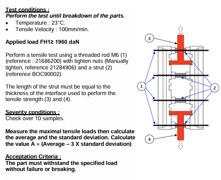
The test was performed at 23°C, using a tensile velocity of 100 mm/min, with the part assembled using an M6 threaded rod, manually tightened nuts and a specified strut/interface arrangement. The test was continued toward breakdown, while the required applied load was defined as FH1 ≥ 1960 daN. Ten samples were evaluated, maximum tensile loads were measured, and the average and standard deviation were calculated, including the statistical value A = Average − 3 × Standard Deviation.
Because 1 daN equals 10 N, 1960 daN corresponds to 19.6 kN.
This is important because the engineering target is no longer simply a tensile-strength value expressed in MPa on a standardized coupon. The complete molded structure must transfer approximately 19.6 kN through its actual interfaces without unacceptable failure.
The 10-sample requirement also changes the development philosophy. One unusually strong prototype is not sufficient. Variation between parts matters. Material homogeneity, charge preparation, fiber distribution, molding conditions and local fiber orientation must be controlled well enough that the production population remains consistently strong.
In other words:
Peak strength is not the same as reliable strength.
The test requirement therefore combines two objectives:
high mechanical capability + low manufacturing variation.
[Suggested chart: “Why Average − 3σ Matters” showing a narrow strength distribution versus a wide distribution with the same average.
Alt text: Statistical comparison showing why consistent High Strength SMC production is important for busbar support tensile qualification.]
Key Takeaways
- The requirement applies to the finished molded component, not just a material coupon.
- FH1 ≥ 1960 daN represents a substantial 19.6 kN structural load.
- Testing 10 parts introduces manufacturing consistency into the acceptance logic.
SUSDURA Long Glass Fiber High Strength SMC: Mechanical Performance
To address the application, SUSDURA used a customized long glass fiber SMC designed for elevated structural performance in the principal reinforcement direction.
The developed material demonstrates a pronounced relationship between reinforcement direction and mechanical properties. Lengthwise flexural strength reaches 250–400 MPa, compared with 70–140 MPa widthwise. Lengthwise tensile strength reaches 140–200 MPa, while lengthwise Charpy notched impact strength is 180–300 kJ/m². Flexural modulus reaches 12–16 GPa in the lengthwise direction. Glass fiber content is specified at 30 ± 3%.
| Property | Direction | SUSDURA High Strength SMC |
|---|---|---|
| Charpy Notched Impact Strength | Lengthwise | 180–300 kJ/m² |
| Charpy Notched Impact Strength | Widthwise | 45–100 kJ/m² |
| Flexural Strength | Lengthwise | 250–400 MPa |
| Flexural Strength | Widthwise | 70–140 MPa |
| Flexural Modulus | Lengthwise | 12–16 GPa |
| Flexural Modulus | Widthwise | 7–9 GPa |
| Tensile Strength | Lengthwise | 140–200 MPa |
| Tensile Strength | Widthwise | 30–60 MPa |
| Specific Gravity | — | 1.68 ± 0.10 g/cm³ |
| Mold Shrinkage | — | <0.4% |
| Glass Fiber Content | — | 30 ± 3% |
| Arc Resistance | — | 180+ s |
| Dielectric Strength | — | 12+ kV/mm |
The tensile values are reported using ASTM D638 methodology in the supplied material data. ASTM D638-22 covers tensile-property testing of reinforced and unreinforced plastics under controlled specimen and test conditions and also emphasizes that preparation, test speed and environment affect measured properties.
ASTM D638-22 official standard page
For flexural performance, ASTM D790 is applicable to reinforced plastics and electrical insulating materials tested in flexure. The current ASTM listing is D790-25.
ASTM D790-25 official standard page
These coupon values characterize the material, but they do not replace finished-part validation.
Key Takeaways
- SUSDURA’s high tensile strength SMC reaches 140–200 MPa lengthwise.
- Flexural strength reaches 250–400 MPa in the primary reinforcement direction.
- Material data should be combined with actual component testing rather than treated as automatic proof of part strength.
Why Directional Strength Is an Engineering Feature, Not a Weakness
The large difference between lengthwise and widthwise properties deserves particular attention because it reveals how this structural SMC material is intended to work.
Conventional chopped-fiber SMC is often discussed as if mechanical properties should be approximately uniform throughout the molded component. In reality, fiber orientation is influenced by sheet architecture, charge placement and material flow during compression molding. For a highly loaded structural component, trying to maximize every property equally in every direction may not be the most efficient solution.
SUSDURA’s approach is to engineer reinforcement around the dominant load path.
Consider the busbar support:
Busbar / Assembly Load
↓
Support Structure
↓
M6 Fastening Region
↓
Composite Load Path
↓
Long Glass Fiber Reinforcement
When more effective reinforcement is positioned along the primary load-transfer direction, the fibers can carry a larger proportion of tensile and bending stress. The objective becomes more specific than simply developing a “stronger resin.”
It becomes:
Place the reinforcement where the component needs strength.
This is why glass-fiber percentage alone is an incomplete indicator of structural performance.
A useful engineering model is:
Structural Performance = Material Formulation × Fiber Length × Fiber Orientation × Interface Quality × Molding Flow × Component Geometry
If any one of these factors is poorly controlled, simply adding more glass fiber may not solve the finished-component problem.
High Strength Is Not Enough: Production Consistency Determines Reliability
For critical electrical components, an exceptional laboratory result is far less valuable than repeatable production.
The customer’s requirement to test ten samples and calculate the average and standard deviation illustrates this clearly. A material may produce a high maximum failure load but still create risk if its strength distribution is too wide.
The development target should therefore move from:
Maximum Strength
to:
Repeatable Structural Strength
This requires process control upstream of the molding press.
At SUSDURA, SMC production integrates controlled raw-material dosing, formulation management, glass-fiber-content verification, sheet-weight control and batch traceability. Online X-ray weight monitoring can be used to improve sheet-weight uniformity, while molding parameters and incoming material conditions are controlled during production.
For high-load parts, several variables deserve special attention:
Material side: resin-paste consistency, fiber content, fiber distribution, maturation and sheet weight.
Molding side: charge weight, charge location, mold temperature, pressure, cure conditions and demolding discipline.
Product side: critical dimensions, hole/insert geometry, assembly interface and tensile validation.
A statistically reliable component therefore depends on much more than the nominal tensile strength of the compound.
For critical electrical structural components, the objective is not to manufacture one unusually strong sample. It is to repeatedly manufacture components whose performance remains safely above the customer’s acceptance requirement.
From Busbar Supports to a Broader High Strength SMC Platform
The significance of this project extends beyond one busbar support.
The same engineering principle—designing fiber architecture and molding strategy around the dominant structural load—can be applied to other electrical components where conventional SMC provides adequate insulation but insufficient mechanical performance.
Potential applications include:
Busbar support insulators, where tensile and bending forces are transferred through bolted interfaces.
Switchgear structural supports, where dimensional stability, dielectric isolation and mechanical rigidity must coexist.
Circuit-breaker structural components, where molded thermoset parts can experience repeated mechanical loading.
Transformer supports and insulating brackets, where stiffness and electrical isolation are both required.
Rail electrical components, where structural integrity, insulation and environmental durability may all be relevant.
Energy-storage and battery structural insulation, particularly where electrical isolation must be integrated with mechanical support.
This is the basis for developing a broader SUSDURA High Strength Structural SMC family rather than treating the material as a one-project formulation.
A useful product architecture could include:
HS-E — High Strength Electrical SMC
HS-LGF — Long Glass Fiber Structural SMC
HS-FR — Flame-Retardant High Strength SMC
HS-CTI — High CTI Structural Electrical SMC
Individual grades would still need to be qualified against their specific application requirements rather than assumed interchangeable.
[Suggested application graphic: “High Strength SMC Applications in Electrical Equipment” showing busbar support, switchgear, breaker, transformer and energy-storage structures.
Alt text: Electrical applications for SUSDURA High Strength SMC and long glass fiber structural SMC.]
Key Takeaways
- The development method is transferable to multiple high-load electrical components.
- High-strength grades can be differentiated by structural and electrical requirements.
- Application-specific validation remains necessary even within the same material family.
Custom High Strength SMC Development at SUSDURA
For demanding structural components, selecting a material from a standard catalog is not always sufficient. SUSDURA’s preferred development process starts with the application rather than the compound number.
A typical development sequence is:
Customer Load Requirement
→ Component Drawing Review
→ Critical Load-Path Identification
→ Material Property Target
→ SMC Formulation Development
→ Fiber Architecture Design
→ Prototype Material Production
→ Compression Molding Trial
→ Finished-Part Mechanical Validation
→ Process Optimization
→ Mass Production
The information supplied during RFQ has a direct effect on development quality.
| RFQ Information | Engineering Purpose |
|---|---|
| 2D/3D component drawing | Geometry and stress review |
| Required tensile/flexural load | Establish mechanical target |
| Primary load direction | Reinforcement strategy |
| Fastener or insert design | Local load-transfer evaluation |
| Wall thickness and ribs | Flow and stiffness evaluation |
| Dielectric requirement | Electrical formulation |
| CTI requirement | Tracking-resistance target |
| Flame requirement | Flame-retardant system selection |
| Operating temperature | Resin-system selection |
| Environmental conditions | Durability assessment |
| Annual volume | Production and tooling strategy |
This model positions SUSDURA not simply as an SMC material manufacturer, but as an integrated development partner combining material formulation, tooling, compression molding, testing and production.
The result is a more useful engineering conversation: instead of asking whether a generic grade is “strong enough,” both sides can define how strong the actual component must be, in which direction, under what fixture conditions, and with what electrical requirements.
FAQ: High Strength SMC for Electrical Busbar Supports
1. What makes High Strength SMC different from standard electrical SMC?
High Strength SMC is engineered to provide substantially greater structural performance while maintaining the electrical properties required by the application. Depending on the component, development may involve longer glass fibers, controlled fiber orientation, optimized fiber/resin bonding, customized formulation and a compression-molding strategy designed around the dominant load path.
Standard electrical SMC can still provide excellent performance in many applications; high-strength grades become especially valuable when the molded part itself is a mechanically loaded structural member.
2. Does higher glass fiber content automatically mean higher SMC strength?
No. Glass-fiber content is only one variable. Fiber length, orientation, fiber wet-out, fiber/matrix adhesion, molding flow, charge placement and component geometry also affect final performance.
A material with more glass fiber can still perform poorly if reinforcement is unfavorably oriented or if critical areas of the molded component experience excessive stress concentration.
3. Can an SMC material tensile-strength value prove that a busbar support will withstand 1960 daN?
Not by itself. Coupon tensile data are useful for material characterization, but final part performance depends on geometry, thickness, fiber orientation, molding flow, holes, inserts, fasteners and fixture conditions. ASTM itself notes that tensile results are influenced by preparation, test speed and environment.
For this reason, the SUSDURA project used finished-part validation in addition to material-property data.
Conclusion: Engineer the Material Around the Load
High Strength SMC should not be selected from a datasheet alone. For demanding electrical components such as busbar supports, formulation, glass-fiber length, reinforcement direction, charge design, compression flow, component geometry and finished-part validation must be treated as one engineering system.
The busbar-support project demonstrates this approach clearly. The customer required a finished component capable of meeting an FH1 ≥ 1960 daN tensile requirement, together with 10-sample statistical evaluation. SUSDURA responded with a customized long glass fiber SMC offering up to 250–400 MPa lengthwise flexural strength, 140–200 MPa lengthwise tensile strength and electrical insulation performance suitable for further application-specific qualification.
The objective was not simply to put more glass fiber into SMC. It was to put strength where the component needs it.
If your busbar support, switchgear component, circuit-breaker part or other structural electrical component exceeds the mechanical capability of conventional electrical-grade SMC, send SUSDURA your component drawing, required load, load direction, electrical requirements, flame/CTI targets and annual volume.
SUSDURA can evaluate a customized High Strength SMC, ultra-high strength SMC, long glass fiber SMC, high tensile strength SMC, structural SMC material or SMC for busbar support solution from material formulation through molding and finished-part validation.