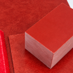
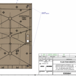
Low Shrinkage SMC Material is increasingly important in switchgear, ACB, MCCB, busbar supports and precision electrical structures where electrical performance alone is no longer enough. A material may meet dielectric strength, CTI and flame-retardancy requirements yet still fail in production if molding shrinkage varies enough to shift hole positions, insert locations, flatness or assembly dimensions.
For precision SMC components, the real engineering challenge is therefore not simply achieving a low shrinkage number. It is achieving low, predictable and repeatable shrinkage without sacrificing electrical, mechanical or molding performance.
TL;DR
- Low shrinkage is critical when SMC parts contain tight tolerances, multiple mounting interfaces, inserts or large reference dimensions.
- A stable 0.08% shrinkage can be more useful than a nominal 0.04% material that varies significantly between batches.
- Low-shrink SMC is created through the interaction of resin chemistry, low-profile additives, fillers, reinforcement, cure behavior and thickening—not one additive alone.
- For electrical applications, shrinkage must be balanced against CTI, dielectric strength, flame retardancy, mechanical strength and processability.
- SUSDURA evaluates low shrinkage from formulation through molding, CMM dimensional inspection and final process capability.
Why Does Low Shrinkage Matter in Precision SMC Components?
SMC is often selected for electrical equipment because it combines insulation, mechanical strength, corrosion resistance, design freedom and high-volume compression molding. However, modern electrical components are becoming increasingly dimension-sensitive.
A switchgear structural wall or insulating panel may contain several mounting holes, molded ribs, metal inserts, busbar interfaces and assembly reference surfaces. Consider an 800 mm reference dimension. A variation of only 0.05% in effective molding shrinkage represents approximately 0.4 mm of dimensional change:
800 mm × 0.0005 = 0.4 mm
For a general FRP cover, this difference may be acceptable. For an ACB mechanism interface, busbar alignment feature, multi-hole mounting structure or insert-molded electrical component, it can be significant.
This is why low mold shrinkage SMC should not be viewed merely as a cosmetic material. In precision applications, it directly affects mold compensation, dimensional tolerances and assembly capability.
The tooling engineer must know how much the compound will shrink when designing the mold. If the material repeatedly behaves around the same shrinkage value, compensation can be engineered into the tool. If the shrinkage changes substantially from batch to batch, even a highly accurate mold cannot completely compensate for that variation.
For precision electrical components, the question is not whether SMC shrinks. The question is whether that shrinkage can be predicted and repeated.
Key Takeaways
- Large dimensions amplify even small shrinkage variations.
- Predictable shrinkage allows accurate mold compensation.
- Dimensional stability starts with the material, not with final inspection.
Internal link suggestion: Learn more about SUSDURA SMC/BMC Compression Molding Capability.
What Is Low Shrinkage SMC Material?
SMC does not simply enter a hot mold and emerge at a smaller size. Its dimensional behavior results from several stages:
Heating → Resin Cure → Polymerization Shrinkage → Thermal Contraction → Demolding → Post-Molding Dimensional Stabilization
Thermosetting polyester and vinyl ester systems experience volumetric change as crosslinking takes place. After curing, the molded component also cools from mold temperature toward ambient temperature. Resin, glass fiber, mineral filler and any metal inserts have different thermal and mechanical behaviors, making final shrinkage a system-level response.
ISO 2577:2007 specifically covers determination of moulding shrinkage and shrinkage after heat treatment for thermosetting moulding materials. ISO also notes that shrinkage information is useful for manufacturing uniformity, mold construction and accurate molded components.
External standard: ISO 2577:2007 — Thermosetting moulding materials — Determination of shrinkage
A commonly cited technical classification is:
| SMC Type | Commonly Cited Shrinkage Range | Primary Engineering Objective |
|---|---|---|
| Standard SMC | ~0.20–0.50% | General structural molding |
| Low-Shrink SMC | ~0.05–0.20% | Dimensional control |
| Low-Profile SMC | <0.05% | Dimensional + surface control |
| Near-Zero SMC | Around zero | Precision molding / surface quality |
| Class-A / Expansion-Type | Slight apparent expansion possible | Premium surface control |
These ranges are technical classifications rather than mandatory ISO acceptance limits. Published SMC literature similarly distinguishes standard, low-shrink, low-profile and expansion-type/Class-A systems.
This distinction is important because low shrinkage SMC material, low-profile SMC, near-zero shrink SMC, and dimensionally stable SMC are related but not necessarily identical engineering specifications.
Key Takeaways
- “Low shrinkage” should be defined by a test method and application requirement.
- Low-profile SMC normally places greater emphasis on surface quality as well as shrinkage.
- A datasheet shrinkage value alone does not define production dimensional capability.
Low Shrinkage vs. Shrinkage Consistency: Which Matters More?
One of the biggest mistakes in selecting low shrink SMC is simply choosing the material with the smallest nominal number.
Consider two hypothetical compounds:
| Material | Nominal / Average Shrinkage | Observed Production Range |
|---|---|---|
| Material A | 0.04% | 0.02–0.08% |
| Material B | 0.08% | 0.075–0.085% |
Material A looks better on a datasheet because 0.04% is lower than 0.08%. Yet for a precision molded component, Material B may actually be easier to engineer.
Why?
A tooling engineer can compensate for a predictable 0.08% shrinkage. It is much more difficult to compensate for a material that behaves at 0.02% in one production condition and approaches 0.08% in another.
This distinction becomes even more important in electrical equipment.
SUSDURA has supported molded SMC components for international electrical equipment manufacturers, including precision ACB applications. In a Schneider Electric ACB program, critical dimensional characteristics achieved approximately Cpk 1.66 under stable mass-production conditions. Such a Cpk result should not be interpreted as a material shrinkage number. It reflects the combined performance of material stability, tooling accuracy, molding control and dimensional inspection.
The more useful engineering equation is therefore:
Low Shrinkage + Low Variation + Stable Molding Process = Dimensional Capability
Not:
Lowest Shrinkage = Best Material
What Controls Shrinkage in SMC Formulation?
Creating low shrinkage sheet molding compound is not as simple as adding more low-shrink additive. Shrinkage develops from an interaction between resin chemistry, reinforcement, filler, cure kinetics, viscosity development and molding conditions.
The resin system establishes the basic polymerization behavior. Unsaturated polyester and vinyl ester systems undergo dimensional change during crosslinking.
Low-profile additives (LPA) or low-shrink additives (LSA) are introduced to compensate for this behavior. Depending on the formulation, systems may use thermoplastic components such as PVAc, PMMA, polystyrene or saturated polyester. Research on unsaturated polyester/LPA systems shows that shrinkage control is connected with cure kinetics, morphology, rheology and phase behavior rather than one simple mechanism.
Mineral fillers, including calcium carbonate in many SMC systems, influence resin volume fraction, rheology, thermal behavior, dimensional response and cost.
Glass fiber content and orientation also matter. During compression molding, material flow changes fiber orientation. As a result, longitudinal and transverse dimensional behavior may not always be identical.
Finally, the cure and thickening systems affect when and how the material flows, gels and develops its final morphology. Mold temperature, cure rate, pressure, charge pattern and material maturity therefore interact with the formulation itself.
That leads to a critical engineering principle:
Mold shrinkage is a material characteristic, but final dimensional stability is a material–tooling–process interaction.
[Suggested diagram: Six Factors Controlling SMC Shrinkage]
Alt text: Resin, low-profile additive, filler, glass fiber, cure system and thickening system controlling low shrinkage SMC performance.
Key Takeaways
- Low shrinkage is created by the complete formulation system.
- Fiber orientation and molding flow can influence directional dimensions.
- Formulation and molding conditions must be developed together.
Internal link suggestion: Learn more about SUSDURA Custom SMC Material Formulation Development.