A French power-industry customer required a large SMC electrical enclosure door panel measuring approximately 600 × 900 mm with a nominal wall thickness of only 2 mm. The challenge was not simply producing an SMC junction box, SMC junction cabinet, or SMC electrical cabinet. The finished enclosure also had to achieve the required IK10 electrical enclosure impact performance while minimizing warpage, local cracking and dimensional instability. For SUSDURA, the solution required combining thin wall SMC molding, SMC panel reinforcement, structural rib engineering and controlled post-molding stabilization rather than simply increasing material thickness.
TL;DR
- The enclosure door measured approximately 600 × 900 mm while maintaining a nominal 2 mm wall thickness.
- IK10 represents an impact energy level of 20 J under the IEC 62262 IK classification system.
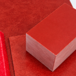
- SUSDURA introduced a glass-fiber reinforcement layer between SMC charges to improve load distribution and crack resistance.
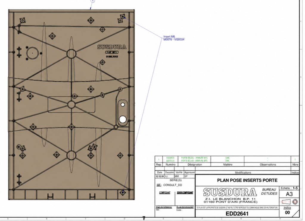
- A backside rib network reduced unsupported panel span and increased structural stiffness.
- A dedicated post-molding cooling and dimensional stabilization fixture was used to control thermal contraction and panel warpage.
Project Requirements: A 600 × 900 mm Panel with Only 2 mm Wall Thickness
For a conventional enclosure, impact resistance can often be improved by increasing wall thickness. That approach was not preferred for this project.
The customer required an approximately 600 × 900 mm enclosure door with a nominal thickness of only 2 mm. At this size, the engineering issue is not simply whether the SMC compound has sufficient tensile or flexural strength. The interaction between panel span, fiber orientation, molded geometry, ribs, residual molding stress and cooling shrinkage becomes increasingly important.
| Requirement | Project Target |
|---|---|
| Application | Electrical junction cabinet / enclosure |
| Market | France |
| Material | Thermoset SMC composite |
| Approx. panel size | 600 × 900 mm |
| Nominal wall thickness | 2.0 mm |
| Mechanical requirement | IK10 impact performance |
| IK10 impact energy | 20 J |
| Primary structural risk | Local deflection / impact cracking |
| Primary dimensional risk | Panel warpage |
| Manufacturing objective | Stable and repeatable production |
According to IEC 62262, the IK code classifies the degree of protection provided by electrical equipment enclosures against external mechanical impacts. IK10 corresponds to a 20 J impact energy level.
The relevant hammer and impact test methods used for electrotechnical products are addressed by IEC 60068-2-75, which defines standardized impact test methods and specified impact-energy levels.
IEC 62262 — Degrees of protection against external mechanical impacts
IEC 60068-2-75 — Hammer tests
This meant SUSDURA had to engineer the enclosure as a complete system:
Material → Reinforcement → Geometry → Mold Filling → Curing → Cooling → Dimensional Control → Impact Validation
Key Takeaways
- Large panel size combined with a 2 mm wall creates a significantly different engineering problem from a conventional thick-wall enclosure.
- IK10 performance cannot be evaluated from SMC material strength alone; the finished enclosure structure is what matters.
- Dimensional stability had to be considered at the same time as impact resistance.
Internal link suggestion: Learn more about SUSDURA SMC/BMC Compression Molding Capability.
Engineering Challenge: IK10 Impact Resistance vs. Thin-Wall Stability
A 2 mm panel covering approximately 0.54 m² has relatively little section thickness available to resist bending. As unsupported span increases, the panel becomes more sensitive to flexing, localized impact loading and residual molding stress.
Three engineering risks therefore had to be addressed.
1. Local Deflection Under Impact
Mechanical impact introduces concentrated energy into a relatively small area of the panel:
Impact → Local Deflection → Stress Concentration → Load Transfer
If the structure cannot distribute that load efficiently, the impact zone can develop matrix cracking, fiber/matrix interface damage or permanent deformation.
2. Stress Concentration Around Structural Features
The door also contains ribs, corners, mounting features and functional interfaces. A rib can improve stiffness, but an improperly designed rib can transfer stress directly into a thin 2 mm skin.
Particular attention therefore had to be paid to:
- rib thickness;
- rib height;
- rib spacing;
- fillet radius;
- rib intersections;
- transition from rib to nominal wall.
3. Warpage After Demolding
Compression molding does not end when the press opens.
During cooling, differences in fiber orientation, local thickness, rib geometry and temperature can produce non-uniform shrinkage:
Molding Stress + Thermal Contraction + Fiber Orientation → Residual Stress → Warpage
For an SMC enclosure design with hinges, sealing surfaces and locking points, even a mechanically strong panel can become unacceptable if the door no longer maintains the required geometry.
This is why SMC panel warpage control became one of the central requirements of the project.
Key Takeaways
- High material strength does not automatically guarantee good IK10 performance.
- Rib geometry must increase stiffness without creating new stress concentration points.
- Post-molding thermal contraction must be controlled on large thin-wall SMC parts.
Internal link suggestion: Learn more about SUSDURA SMC Tooling & Mold Engineering.
Solution 1: Glass-Fiber Reinforced SMC Lay-Up for Impact Load Distribution
Instead of solving the problem by increasing the entire wall thickness, SUSDURA modified the charge lay-up.
A reinforcing glass-fiber layer was positioned between the upper and lower SMC material charges before compression molding.
The simplified structure was:
SMC Layer
↓
Glass-Fiber Reinforcement Layer
↓
SMC Layer
Depending on the actual reinforcement construction used, this layer may technically be described as a glass-fiber scrim, woven glass fabric or another continuous glass reinforcement. The final terminology should match the production material specification.
The purpose of this architecture was not simply to add more glass fiber.
It was intended to change how impact loads were transmitted through the panel.
Improved Load Distribution
The reinforcement provides a more continuous load path across the panel and helps distribute concentrated loading away from the immediate impact point.
Crack Propagation Resistance
SMC itself contains chopped glass reinforcement, but an additional continuous reinforcement layer can help bridge highly stressed regions and reduce the tendency for a local matrix crack to propagate rapidly across the panel.
Improved Structural Integrity
The reinforced laminate therefore gave the 2 mm panel additional structural support without redesigning the entire door around a substantially thicker nominal section.
This is an important distinction for thin wall SMC enclosure engineering: the goal was not simply to add material, but to place reinforcement where it generated the greatest structural benefit.
Key Takeaways
- SUSDURA used a reinforced SMC laminate rather than relying only on standard chopped-fiber SMC.
- Continuous reinforcement helped improve load transfer across the thin panel.
- Reinforcement placement was treated as part of the molding architecture rather than as an afterthought.
Internal link suggestion: Learn more about Custom SMC Material Development and Formulation.
Solution 2: Backside Rib Engineering to Reduce Unsupported Panel Span
Material reinforcement alone could not solve the problem.
A 600 × 900 mm flat surface with a 2 mm nominal wall still has a relatively large unsupported span. SUSDURA therefore incorporated an engineered backside rib network into the enclosure door.
The important concept was not simply “adding more ribs.”
The engineering objective was to divide one large flexible surface into several smaller structural zones.
Without Structural Ribs
Large Unsupported Surface
↓
Higher Local Bending
↓
Greater Deflection
With an Engineered Rib Network
600 × 900 mm Panel
↓
Multiple Smaller Supported Zones
↓
Shorter Effective Span
↓
Lower Panel Deflection
Rib-to-wall transitions were also important.
If a relatively thick rib joins a 2 mm skin abruptly, differences in section stiffness and molding shrinkage can create a stress concentration near the rib root. Fillet geometry, rib spacing and intersection design therefore need to be considered together.
For this project, the rib network served two purposes:
Impact loading: distribute loads into a larger structural area.
Dimensional stability: increase bending stiffness so that the panel is less sensitive to distortion during handling, assembly and service.
This combination of SMC panel reinforcement and structural rib design was essential to achieving the required performance without making the complete enclosure substantially thicker.
Key Takeaways
- The objective of rib design was to reduce unsupported span rather than simply maximize rib quantity.
- Rib geometry and transitions influence both impact performance and residual stress.
- Material reinforcement and geometry were engineered as one structural system.
Solution 3: Post-Molding Cooling Fixture for SMC Panel Warpage Control
One of the most important lessons from large SMC compression molding enclosure production is that a part can leave the compression mold in the correct shape and still distort later.
At demolding temperature, the thermoset structure is cured, but the component still needs to cool toward ambient temperature.
During this stage, the panel experiences:
- thermal contraction;
- redistribution of residual molding stresses;
- different cooling rates between ribs and nominal walls;
- anisotropic shrinkage related to glass-fiber orientation.
For a large 2 mm panel, free cooling can allow these stresses to translate into bowing or twisting.
SUSDURA therefore developed a dedicated post-molding cooling and dimensional stabilization fixture.
The production sequence became:
Compression Molding
↓
Controlled Demolding
↓
Transfer to Cooling Fixture
↓
Geometric Constraint During Cooling
↓
Stress Stabilization
↓
Dimensional Inspection
The fixture was designed to support critical panel surfaces and maintain key geometry while the door cooled.
This was especially important around sealing surfaces, edges, mounting locations and areas affecting door alignment.
Rather than trying to correct a distorted component after cooling, the process was designed to prevent uncontrolled deformation during the period when the panel was most vulnerable to dimensional movement.
That distinction is central to effective SMC panel warpage control.
Key Takeaways
- Demolding does not represent the end of dimensional stabilization.
- Large thin-wall SMC parts can distort during cooling even if the mold geometry is correct.
- A dedicated stabilization fixture helps convert dimensional control into a repeatable production process.
Engineering Validation: From Prototype Failure Modes to the Final Design
A development project such as this should not simply jump from design to “PASS.”
The more useful engineering process is to compare successive design conditions and identify which modification solves which failure mode.
The following dataset illustrates how such validation can be presented.
Important editorial note: The numerical values below are illustrative engineering data created to show the recommended reporting structure. They are not a SUSDURA certified test report and should be replaced with actual project inspection and laboratory records before public release.
[Suggested table: Illustrative Prototype Validation Results]
| Validation Item | Prototype A | Prototype B | Final Design* |
|---|---|---|---|
| Nominal panel thickness | 2.0 mm | 2.0 mm | 2.0 mm |
| Panel size | 600 × 900 mm | 600 × 900 mm | 600 × 900 mm |
| Additional glass reinforcement | No | Yes | Yes |
| Optimized backside rib network | Partial | Yes | Yes |
| Controlled cooling fixture | No | No | Yes |
| Impact energy | 20 J | 20 J | 20 J |
| Visible through-crack after impact | Yes | No | No |
| Illustrative residual local deformation | 4.2 mm | 1.8 mm | 0.8 mm |
| Illustrative flatness deviation after 24 h | 5.8 mm | 3.2 mm | 1.4 mm |
| Hinge / locking function after test | Functional | Functional | Functional |
| Engineering disposition | Redesign | Dimensional improvement required | Target condition achieved |
*Illustrative data only; replace with actual test report results.
This type of validation table tells a stronger engineering story than simply stating that “the enclosure passed IK10.”
Prototype A demonstrates why material and geometry cannot be evaluated independently.
Prototype B indicates that reinforcement and rib optimization can substantially improve impact behavior while dimensional stability may still require additional process control.
The final configuration then introduces the cooling stabilization fixture to address the remaining warpage mechanism.
For actual production validation, SUSDURA would ideally record additional parameters such as:
| Production Control Item | Example Reporting Format* |
|---|---|
| Nominal thickness | 2.00 mm |
| Illustrative measured thickness range | 1.94–2.07 mm |
| Illustrative 24 h panel flatness | 1.1–1.8 mm |
| Illustrative diagonal difference | ≤1.5 mm |
| Impact energy | 20 J |
| Through-crack | None observed |
| Hinge function | Normal |
| Locking function | Normal |
| Panel installation | Acceptable |
*Example format only. Replace numerical values with actual production inspection records.
The key point is that IK performance and dimensional performance should be verified separately.
IEC 62262 defines the IK classification, while the exact acceptance criteria applicable to a finished electrical enclosure may also depend on the relevant product standard and customer specification.
Key Takeaways
- Prototype comparison provides stronger evidence than a simple PASS statement.
- Impact performance and dimensional stability should be evaluated independently.
- Actual published data should come from controlled SUSDURA or third-party test records.
Why Increasing the SMC Wall Thickness Was Not the Preferred Solution
The simplest engineering response might have been to increase the panel from 2 mm to 3 mm, 4 mm or more.
That would potentially increase bending stiffness, but it would also change the product in several other ways.
Greater thickness can mean:
- increased material consumption;
- increased enclosure weight;
- different SMC charge requirements;
- altered mold filling behavior;
- different curing and heat-transfer characteristics;
- higher material cost;
- possible changes to hinge, seal and assembly dimensions.
More importantly, adding thickness does not necessarily address the original cause of warpage.
If residual stress, fiber orientation or uncontrolled cooling is responsible for panel distortion, simply adding more SMC may make the part heavier without fully solving the process problem.
For this reason, the project philosophy became:
Do not simply make the panel thicker. Make the 2 mm structure work more efficiently.
The resulting design combined four engineering layers:
Material Architecture
+
Structural Geometry
+
Compression Molding Control
+
Post-Molding Dimensional Stabilization
This systems-level approach is particularly important for a custom SMC electrical enclosure where impact performance, electrical insulation, weatherability, assembly and dimensional stability often need to be achieved simultaneously.
Key Takeaways
- More material is not always the most efficient engineering solution.
- Thickness changes affect weight, cost, molding behavior and assembly geometry.
- The final solution treated material, structure and manufacturing as one system.
Engineering Result: One Problem Required Three Different Forms of Reinforcement
The final engineering concept did not rely on a single change.
| Engineering Challenge | SUSDURA Engineering Solution |
|---|---|
| 2 mm nominal wall | Reinforced thin-wall SMC architecture |
| 600 × 900 mm surface | Backside structural rib network |
| IK10 impact requirement | Improved impact-load distribution |
| Local crack propagation risk | Additional glass-fiber reinforcement |
| Excessive unsupported span | Optimized rib layout |
| Rib-root stress concentration | Controlled rib transitions and fillet design |
| Thermal contraction | Post-molding stabilization process |
| Panel warpage | Dedicated cooling fixture |
| Dimensional repeatability | Fixed molding, cooling and inspection process |
| Mass-production requirement | Standardized manufacturing controls |
The project therefore demonstrates an important principle in SMC enclosure design:
Impact resistance is not purely a material property, and dimensional stability is not purely a tooling problem.
Both are outcomes of the complete manufacturing system.
For an experienced SMC enclosure manufacturer or SMC junction box manufacturer, successful development requires coordination between compound formulation, charge placement, mold design, rib geometry, compression molding parameters, post-molding fixtures and inspection.
Key Takeaways
- Three different engineering mechanisms were used: laminate reinforcement, geometric reinforcement and process stabilization.
- The design targets impact behavior and dimensional stability simultaneously.
- This integrated approach is more scalable for mass production than post-process correction.
FAQ: SMC Electrical Enclosure and IK10 Engineering
1. Can a 2 mm SMC electrical enclosure achieve IK10 impact resistance?
Potentially, yes, but wall thickness alone cannot determine IK performance. The finished enclosure geometry, SMC formulation, reinforcement architecture, rib design, mounting conditions and impact-test configuration all affect the result. IK10 represents a 20 J impact-energy classification under IEC 62262.
2. How can warpage be reduced in a large thin-wall SMC panel?
Effective SMC panel warpage control requires attention to material flow, fiber orientation, wall and rib geometry, mold temperature, cure conditions, demolding and cooling. For this project, SUSDURA added a dedicated post-molding dimensional stabilization fixture to support the panel during cooling.
3. Why use glass reinforcement between SMC layers?
An additional continuous glass reinforcement layer can help distribute local loads, bridge highly stressed regions and improve structural integrity. The reinforcement structure and placement should be engineered specifically for the component rather than treated as a universal solution for every FRP electrical enclosure.
Conclusion: Engineering the Complete SMC Enclosure System
This French power-industry project demonstrates why the development of an SMC electrical enclosure, SMC junction box, SMC junction cabinet, SMC electrical cabinet, fiberglass electrical enclosure, FRP electrical enclosure or composite electrical enclosure cannot be reduced to selecting a strong SMC grade.
For a 600 × 900 mm thin wall SMC enclosure, achieving the required IK10 electrical enclosure, IK10 junction box or IK10 electrical cabinet performance meant addressing impact-load distribution, crack propagation, panel stiffness and cooling distortion simultaneously.
SUSDURA combined thin wall SMC molding, SMC panel reinforcement, engineered backside ribs, SMC panel warpage control and a dedicated post-molding cooling fixture to create a more robust manufacturing strategy. This integrated approach is particularly valuable when developing an impact resistant electrical enclosure, SMC compression molding enclosure or custom SMC electrical enclosure where weight, wall thickness, dimensional stability and mechanical performance must be balanced.
As an SMC enclosure manufacturer and SMC junction box manufacturer, SUSDURA can support projects beyond molding alone—from custom SMC material development and SMC enclosure design through tooling, compression molding, dimensional validation, electrical and mechanical testing, and mass production.
If you are developing a thin-wall electrical enclosure, junction box or cabinet with demanding IK impact, dimensional, flame-retardant, weather-resistance or electrical-insulation requirements, contact SUSDURA with your drawings, target wall thickness, enclosure dimensions, test standards and annual volume for an engineering review.